HP ProLiant MicroServer Gen8 HP ProLiant MicroServer Gen8 Maintenance and Serv - Page 53
System board
 |
View all HP ProLiant MicroServer Gen8 manuals
Add to My Manuals
Save this manual to your list of manuals |
Page 53 highlights
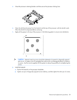
2. Close the processor retaining bracket, and then secure the processor locking lever. 3. Clean the old thermal grease from the heatsink with the alcohol swab. Allow the alcohol to evaporate before continuing. 4. Apply all the grease to the top of the processor in the following pattern to ensure even distribution. 5. Install the heatsink ("Heatsink" on page 49). 6. Install the system board assembly (on page 30). 7. Install the chassis cover (on page 27). 8. Connect each power cord to the server. 9. Connect each power cord to the power source. 10. Press the Power On/Standby button. The server exits standby mode and applies full power to the system. The system power LED changes from amber to green. System board CAUTION: To avoid ESD damage, when removing electrostatic-sensitive components from the failed system board, place the components on a static-dissipating work surface or inside separate antistatic bags. Removal and replacement procedures 53
-
 1
1 -
2
-
3
-
4
-
5
-
6
-
7
-
8
-
9
-
10
-
11
-
12
-
13
-
14
-
15
-
16
-
17
-
18
-
19
-
20
-
21
-
22
-
23
-
24
-
25
-
26
-
27
-
28
-
29
-
30
-
31
-
32
-
33
-
34
-
35
-
36
-
37
-
38
-
39
-
40
-
41
-
42
-
43
-
44
-
45
-
46
-
47
-
 48
48 -
 49
49 -
 50
50 -
 51
51 -
 52
52 -
 53
53 -
 54
54 -
 55
55 -
 56
56 -
 57
57 -
 58
58 -
59
-
60
-
61
-
62
-
63
-
64
-
65
-
66
-
67
-
68
-
69
-
70
-
71
-
72
-
73
-
74
-
75
-
76
-
77
-
78
-
79
-
80
-
81
-
82
-
83
-
84
-
85
-
86
-
87
 |
 |
