HP ProLiant MicroServer Gen8 HP ProLiant MicroServer Gen8 Maintenance and Serv - Page 59
Press the Power On/Standby button., Install the DIMMs. - won t startup
 |
View all HP ProLiant MicroServer Gen8 manuals
Add to My Manuals
Save this manual to your list of manuals |
Page 59 highlights
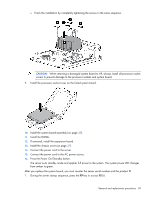
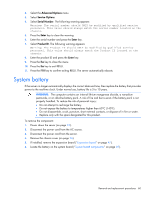
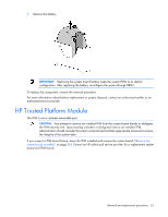
c. Finish the installation by completely tightening the screws in the same sequence. CAUTION: When returning a damaged system board to HP, always install all processor socket covers to prevent damage to the processor sockets and system board. 9. Install the processor socket cover on the failed system board. 10. Install the system board assembly (on page 30). 11. Install the DIMMs. 12. If removed, install the expansion board. 13. Install the chassis cover (on page 27). 14. Connect the power cord to the server. 15. Connect the power cord to the AC power source. 16. Press the Power On/Standby button. The server exits standby mode and applies full power to the system. The system power LED changes from amber to green. After you replace the system board, you must re-enter the server serial number and the product ID. 1. During the server startup sequence, press the F9 key to access RBSU. Removal and replacement procedures 59
-
 1
1 -
2
-
3
-
4
-
5
-
6
-
7
-
8
-
9
-
10
-
11
-
12
-
13
-
14
-
15
-
16
-
17
-
18
-
19
-
20
-
21
-
22
-
23
-
24
-
25
-
26
-
27
-
28
-
29
-
30
-
31
-
32
-
33
-
34
-
35
-
36
-
37
-
38
-
39
-
40
-
41
-
42
-
43
-
44
-
45
-
46
-
47
-
48
-
49
-
50
-
51
-
52
-
53
-
 54
54 -
 55
55 -
 56
56 -
 57
57 -
 58
58 -
 59
59 -
 60
60 -
 61
61 -
 62
62 -
 63
63 -
 64
64 -
65
-
66
-
67
-
68
-
69
-
70
-
71
-
72
-
73
-
74
-
75
-
76
-
77
-
78
-
79
-
80
-
81
-
82
-
83
-
84
-
85
-
86
-
87
 |
 |
