HP Slate 10 HD 3500ca HP Slate10 HD and HP Slate7 HD Maintenance and Service G - Page 43
HP Slate7 HD, Back cover, Card Reader slot
 |
View all HP Slate 10 HD 3500ca manuals
Add to My Manuals
Save this manual to your list of manuals |
Page 43 highlights
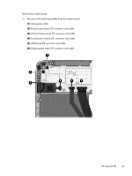
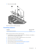
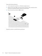
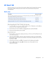
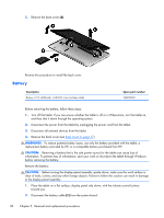
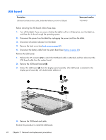
HP Slate7 HD There are as many as 16 screws that must be removed, replaced, and/or loosened when servicing the HP Slate7 HD tablet. Make special note of each screw size and location during removal and replacement. Back cover Description Spare part number Back cover (includes card reader slot, SIM slot cover, grounding pads and tape, power button actuator, shielding, volume button actuator, webcam lens, and wireless antenna) In bright red finish (includes WiFi antenna cable and transceivers) 744579-001 In silver slate finish (includes WiFi antenna cable and transceivers) 743041-001 Display panel assembly, 7.0-in, LCD, TFT, TouchScreen (includes display panel cable) 743046-001 Before disassembling the HP Slate7 HD tablet, follow these steps: 1. Turn off the tablet. If you are unsure whether the tablet is off or in Hibernation, turn the tablet on, and then shut it down through the operating system. 2. Disconnect the power from the tablet by unplugging the power cord from the tablet. 3. Disconnect all external devices from the tablet. Remove the back cover: 1. Place the tablet on a flat surface, display panel side up, with the micro SD Card Reader slot and micro SIM slot toward you. 2. Insert a case utility tool (1) or similar thin, plastic tool between the back cover and the display panel assembly. The first insertion point should be in the left side of the tablet near the micro SD Card Reader slot (2). 3. Lift the left side of the back cover (3) until it separates from the display panel assembly. 4. Lift the top (4) and the bottom edges (5) of the back cover until they detach from the display panel assembly. HP Slate7 HD 37
-
 1
1 -
2
-
3
-
4
-
5
-
6
-
7
-
8
-
9
-
10
-
11
-
12
-
13
-
14
-
15
-
16
-
17
-
18
-
19
-
20
-
21
-
22
-
23
-
24
-
25
-
26
-
27
-
28
-
29
-
30
-
31
-
32
-
33
-
34
-
35
-
36
-
37
-
 38
38 -
 39
39 -
 40
40 -
 41
41 -
 42
42 -
 43
43 -
 44
44 -
 45
45 -
 46
46 -
 47
47 -
 48
48 -
49
-
50
-
51
-
52
-
53
-
54
-
55
-
56
-
57
-
58
-
59
-
60
-
61
-
62
-
63
 |
 |
