HP Stream 11-y000 Maintenance and Service Guide - Page 55
Display assembly, Flex the inside edges of the top edge
 |
View all HP Stream 11-y000 manuals
Add to My Manuals
Save this manual to your list of manuals |
Page 55 highlights
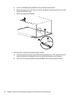
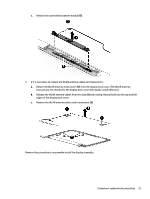
Display assembly NOTE: The display assembly is spared at the subcomponent level only. For more display assembly spare part information, see the individual removal subsections and see Display assembly subcomponents on page 18. Before removing the display assembly, follow these steps: 1. Prepare the computer for disassembly (Preparation for disassembly on page 26). 2. Remove the keyboard/top cover (see Keyboard/top cover on page 28). 3. Disconnect the battery (see Battery on page 34). Remove the display assembly: 1. Remove the four Phillips M2.4 × 4.6 screws (1) that secure the display assembly to the bottom cover. 2. Release the power connector cable (2) from the right hinge area. 3. Remove the display assembly (3). 4. If it is necessary to replace the display bezel or any of the display assembly subcomponents: a. Flex the inside edges of the top edge (1), the left and right sides (2), and the bottom edge (3) of the display bezel until the bezel disengages from the display back cover. b. Remove the display bezel (4). Component replacement procedures 47
-
 1
1 -
2
-
3
-
4
-
5
-
6
-
7
-
8
-
9
-
10
-
11
-
12
-
13
-
14
-
15
-
16
-
17
-
18
-
19
-
20
-
21
-
22
-
23
-
24
-
25
-
26
-
27
-
28
-
29
-
30
-
31
-
32
-
33
-
34
-
35
-
36
-
37
-
38
-
39
-
40
-
41
-
42
-
43
-
44
-
45
-
46
-
47
-
48
-
49
-
 50
50 -
 51
51 -
 52
52 -
 53
53 -
 54
54 -
 55
55 -
 56
56 -
 57
57 -
 58
58 -
 59
59 -
 60
60 -
61
-
62
-
63
-
64
-
65
-
66
-
67
-
68
-
69
-
70
-
71
-
72
-
73
-
74
-
75
-
76
-
77
 |
 |
