HP Stream 11-y000 Maintenance and Service Guide - Page 59
Release the WLAN antenna cables from the clips
 |
View all HP Stream 11-y000 manuals
Add to My Manuals
Save this manual to your list of manuals |
Page 59 highlights
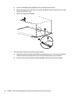
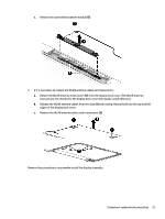
c. Remove the camera/microphone module (3). 9. If it is necessary to replace the WLAN antenna cables and transceivers: a. Detach the WLAN antenna transceivers (1) from the display back cover. (The WLAN antenna transceivers are attached to the display back cover with double-sided adhesive.) b. Release the WLAN antenna cables from the clips (2) and routing channel built into the top and left edges of the display back cover. c. Remove the WLAN antenna cables and transceivers (3). Reverse this procedure to reassemble install the display assembly. Component replacement procedures 51
-
 1
1 -
2
-
3
-
4
-
5
-
6
-
7
-
8
-
9
-
10
-
11
-
12
-
13
-
14
-
15
-
16
-
17
-
18
-
19
-
20
-
21
-
22
-
23
-
24
-
25
-
26
-
27
-
28
-
29
-
30
-
31
-
32
-
33
-
34
-
35
-
36
-
37
-
38
-
39
-
40
-
41
-
42
-
43
-
44
-
45
-
46
-
47
-
48
-
49
-
50
-
51
-
52
-
53
-
 54
54 -
 55
55 -
 56
56 -
 57
57 -
 58
58 -
 59
59 -
 60
60 -
 61
61 -
 62
62 -
 63
63 -
 64
64 -
65
-
66
-
67
-
68
-
69
-
70
-
71
-
72
-
73
-
74
-
75
-
76
-
77
 |
 |

c.
Remove the camera/microphone module
(3)
.
9.
If it is necessary to replace the WLAN antenna cables and transceivers:
a.
Detach the WLAN antenna transceivers
(1)
from the display back cover. (The WLAN antenna
transceivers are attached to the display back cover with double-sided adhesive.)
b.
Release the WLAN antenna cables from the clips
(2)
and routing channel built into the top and left
edges of the display back cover.
c.
Remove the WLAN antenna cables and transceivers
(3)
.
Reverse this procedure to reassemble install the display assembly.
Component replacement procedures
51