HP dx2390 Hardware Reference Guide - dx2390 Microtower Model - Page 21
Populating DIMM Sockets,
 |
View all HP dx2390 manuals
Add to My Manuals
Save this manual to your list of manuals |
Page 21 highlights
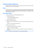
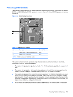
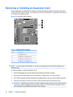
Populating DIMM Sockets There are two DIMM sockets on the system board, with one socket per channel. The sockets are labeled DIMM1 and DIMM2. Socket DIMM1 operates in memory channel A. Socket DIMM2 operates in memory channel B. Figure 2-6 DIMM Socket Locations Table 2-1 DIMM Socket Locations Item Description 1 DIMM1 socket, Channel A (populate first) 2 DIMM2 socket, Channel B NOTE: A DIMM must occupy the DIMM1 socket. Socket Color Blue Blue The system will automatically operate in single channel mode, dual channel mode, or flex mode, depending on how the DIMMs are installed. ● The system will operate in single channel mode if the DIMM sockets are populated in one channel only. ● The system will operate in a higher-performing dual channel mode if the memory capacity of the DIMM in Channel A is equal to the total memory capacity of the DIMM in Channel B. ● The system will operate in flex mode if the memory capacity of the DIMM in Channel A is not equal to the memory capacity of the DIMM in Channel B. In flex mode, the channel populated with the least amount of memory describes the total amount of memory assigned to dual channel and the remainder is assigned to single channel. If one channel will have more memory than the other, the larger amount should be assigned to Channel A. ● In any mode, the maximum operational speed is determined by the slowest DIMM in the system. Installing Additional Memory 15
-
 1
1 -
2
-
3
-
4
-
5
-
6
-
7
-
8
-
9
-
10
-
11
-
12
-
13
-
14
-
15
-
 16
16 -
 17
17 -
 18
18 -
 19
19 -
 20
20 -
 21
21 -
 22
22 -
 23
23 -
 24
24 -
 25
25 -
 26
26 -
27
-
28
-
29
-
30
-
31
-
32
-
33
-
34
-
35
-
36
-
37
-
38
-
39
-
40
-
41
-
42
-
43
-
44
-
45
-
46
-
47
-
48
-
49
-
50
-
51
-
52
-
53
-
54
-
55
-
56
-
57
 |
 |
