HP dx2390 Hardware Reference Guide - dx2390 Microtower Model - Page 37
CAUTION, Removing Bezel Blanks, on Installing, Additional Drives
 |
View all HP dx2390 manuals
Add to My Manuals
Save this manual to your list of manuals |
Page 37 highlights
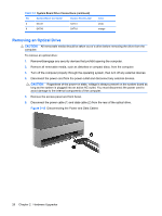
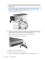
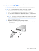
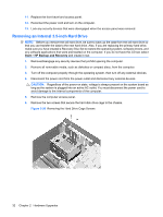
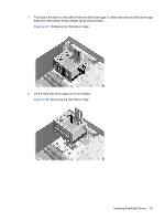
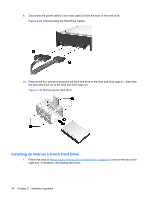
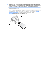
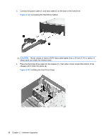
4. Disconnect the power cord from the power outlet and disconnect any external devices. CAUTION: Regardless of the power-on state, voltage is always present on the system board as long as the system is plugged into an active AC outlet. You must disconnect the power cord to avoid damage to the internal components of the computer. 5. Remove the access panel and front bezel. 6. If you are installing a diskette drive or media card reader in a bay covered by a bezel blank, remove the front bezel then remove the bezel blank. See Removing Bezel Blanks on page 12 for more information. 7. If you are adding a drive to an empty drive bay for the first time, you must remove the knockout plate from the bay. To do so, insert a flat screwdriver into the knockout plate slot and rotate the screwdriver to break the knockout plate out of the chassis. Discard the knockout plate. 8. If the new drive has screws installed on the sides of the drive, remove them before inserting the drive into the chassis. 9. Slide the drive in through the front of the chassis (1) until the bezel on the drive is evenly aligned with the computer front bezel and install the two M3 metric retainer screws (2) as shown in the illustration below. NOTE: Extra drive retainer screws are provided on the interior of the front bezel if needed. The M3 metric retainer screws for diskette drives or media card readers are black. Refer to Installing Additional Drives on page 24 for an illustration of the retainer screws location. Figure 2-25 Installing a 3.5-inch Device (Media Card Reader Shown) 10. Connect the appropriate drive cables: a. If installing a diskette drive, connect the power and data cables to the rear of the drive and connect the other end of the data cable to the connector on the system board labeled FDD1. b. If installing a media card reader, connect the USB cable from the media card reader to the USB connector on the system board labeled JUSB2. NOTE: Refer to System Board Drive Connections on page 25 for an illustration of the system board drive connectors. Installing Additional Drives 31
-
 1
1 -
2
-
3
-
4
-
5
-
6
-
7
-
8
-
9
-
10
-
11
-
12
-
13
-
14
-
15
-
16
-
17
-
18
-
19
-
20
-
21
-
22
-
23
-
24
-
25
-
26
-
27
-
28
-
29
-
30
-
31
-
 32
32 -
 33
33 -
 34
34 -
 35
35 -
 36
36 -
 37
37 -
 38
38 -
 39
39 -
 40
40 -
 41
41 -
 42
42 -
43
-
44
-
45
-
46
-
47
-
48
-
49
-
50
-
51
-
52
-
53
-
54
-
55
-
56
-
57
 |
 |