HP dx2390 Hardware Reference Guide - dx2390 Microtower Model - Page 34
Connecting the Power and Data Cables, Installing the Optical Drive
 |
View all HP dx2390 manuals
Add to My Manuals
Save this manual to your list of manuals |
Page 34 highlights
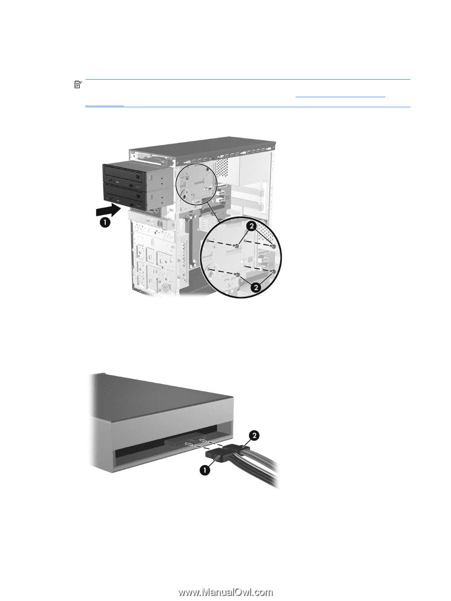
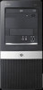
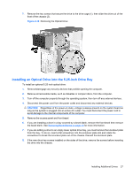
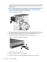
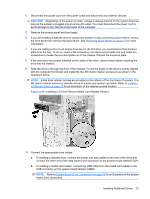
9. Slide the drive in through the front of the chassis (1) until the bezel on the drive is evenly aligned with the computer front bezel and install the two M3 metric retainer screws (2) as shown in the illustration below. NOTE: Extra drive retainer screws are provided on the interior of the front bezel if needed. The M3 metric retainer screws for optical drives are black. Refer to Installing Additional Drives on page 24 for an illustration of the retainer screws location. Figure 2-20 Installing the Optical Drive 10. If the system configuration includes only one optical drive, connect the SATA data cable to the white system board connector labeled SATA1. If you are adding a second optical drive, connect the SATA data cable to the orange system board connector labeled SATA3. 11. Connect the power cable (1) and data cable (2) to the rear of the optical drive. Figure 2-21 Connecting the Power and Data Cables 12. Replace the front bezel and access panel. 13. Reconnect the power cord and turn on the computer. 14. Lock any security devices that were disengaged when the access panel was removed. 28 Chapter 2 Hardware Upgrades
-
 1
1 -
2
-
3
-
4
-
5
-
6
-
7
-
8
-
9
-
10
-
11
-
12
-
13
-
14
-
15
-
16
-
17
-
18
-
19
-
20
-
21
-
22
-
23
-
24
-
25
-
26
-
27
-
28
-
 29
29 -
 30
30 -
 31
31 -
 32
32 -
 33
33 -
 34
34 -
 35
35 -
 36
36 -
 37
37 -
 38
38 -
 39
39 -
40
-
41
-
42
-
43
-
44
-
45
-
46
-
47
-
48
-
49
-
50
-
51
-
52
-
53
-
54
-
55
-
56
-
57
 |
 |