HP dx2390 Hardware Reference Guide - dx2390 Microtower Model - Page 32
Removing an Optical Drive, CAUTION,
 |
View all HP dx2390 manuals
Add to My Manuals
Save this manual to your list of manuals |
Page 32 highlights
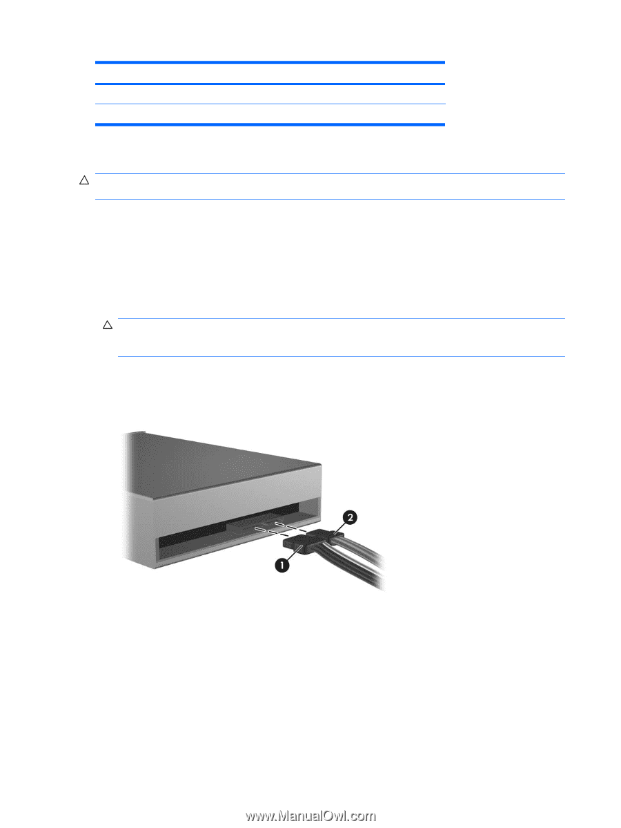
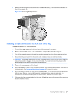
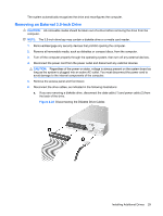
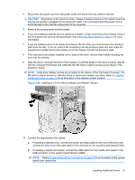
Table 2-3 System Board Drive Connections (continued) No. System Board Connector System Board Label 5 SATA1 SATA1 6 SATA3 SATA3 Color white orange Removing an Optical Drive CAUTION: All removable media should be taken out of a drive before removing the drive from the computer. To remove an optical drive: 1. Remove/disengage any security devices that prohibit opening the computer. 2. Remove all removable media, such as diskettes or compact discs, from the computer. 3. Turn off the computer properly through the operating system, then turn off any external devices. 4. Disconnect the power cord from the power outlet and disconnect any external devices. CAUTION: Regardless of the power-on state, voltage is always present on the system board as long as the system is plugged into an active AC outlet. You must disconnect the power cord to avoid damage to the internal components of the computer. 5. Remove the access panel and front bezel. 6. Disconnect the power cable (1) and data cable (2) from the rear of the optical drive. Figure 2-18 Disconnecting the Power and Data Cables 26 Chapter 2 Hardware Upgrades
-
 1
1 -
2
-
3
-
4
-
5
-
6
-
7
-
8
-
9
-
10
-
11
-
12
-
13
-
14
-
15
-
16
-
17
-
18
-
19
-
20
-
21
-
22
-
23
-
24
-
25
-
26
-
 27
27 -
 28
28 -
 29
29 -
 30
30 -
 31
31 -
 32
32 -
 33
33 -
 34
34 -
 35
35 -
 36
36 -
 37
37 -
38
-
39
-
40
-
41
-
42
-
43
-
44
-
45
-
46
-
47
-
48
-
49
-
50
-
51
-
52
-
53
-
54
-
55
-
56
-
57
 |
 |