HP dx7300 HP Compaq dx7300 Business PC Service Reference Guide, 1st Edition - Page 120
Vertically Oriented Expansion Card
 |
View all HP dx7300 manuals
Add to My Manuals
Save this manual to your list of manuals |
Page 120 highlights
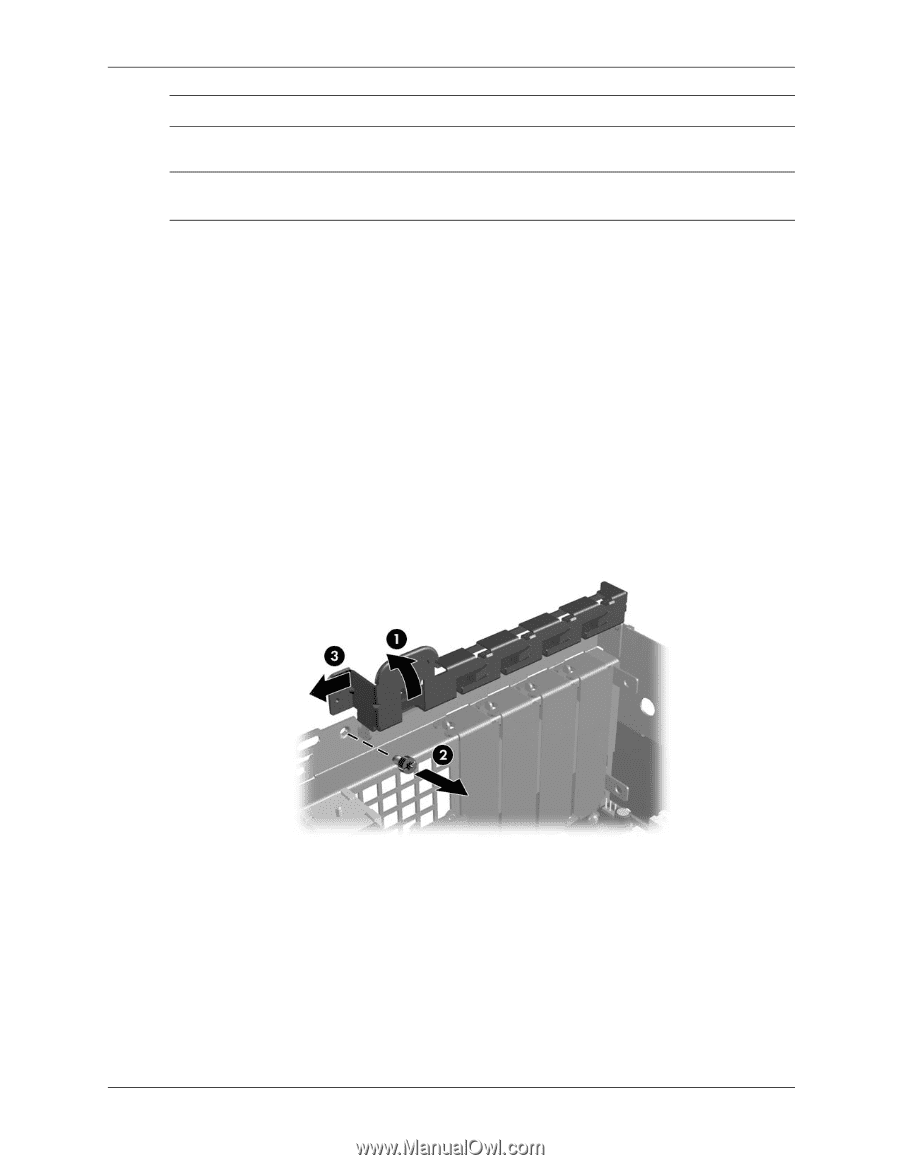
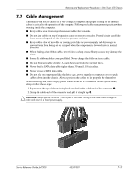
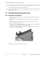
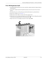
Removal and Replacement Procedures- Slim Tower (ST) Chassis ✎ The computer automatically recognizes the additional memory when the computer is turned on. To reassemble the computer, reverse the removal procedure. ✎ If you normally lock the Smart Cover Lock, use Computer Setup to relock the lock and enable the Smart Cover Sensor. 7.9 Vertically Oriented Expansion Card 7.9.1 Expansion Card Retainer 1. If you have locked the Smart Cover Lock, restart the computer and enter Computer Setup to unlock the lock. 2. Turn off the computer properly through the operating system, then turn off any external devices. 3. Disconnect the power cord from the power outlet and disconnect any external devices. 4. Remove the computer cover (Section 7.5). 5. Release the slot cover retention latch that secures the PCI slot covers by lifting the green tab on the latch and rotating the latch to the full open position 1. 6. Remove the single screw that keeps the card retainer in place 2 and slide the retainer to the left to remove it from the chassis 3. To install the card retainer, reverse the removal procedure. 7-14 433611-001 Service Reference Guide, dx7300
-
 1
1 -
2
-
3
-
4
-
5
-
6
-
7
-
8
-
9
-
10
-
11
-
12
-
13
-
14
-
15
-
16
-
17
-
18
-
19
-
20
-
21
-
22
-
23
-
24
-
25
-
26
-
27
-
28
-
29
-
30
-
31
-
32
-
33
-
34
-
35
-
36
-
37
-
38
-
39
-
40
-
41
-
42
-
43
-
44
-
45
-
46
-
47
-
48
-
49
-
50
-
51
-
52
-
53
-
54
-
55
-
56
-
57
-
58
-
59
-
60
-
61
-
62
-
63
-
64
-
65
-
66
-
67
-
68
-
69
-
70
-
71
-
72
-
73
-
74
-
75
-
76
-
77
-
78
-
79
-
80
-
81
-
82
-
83
-
84
-
85
-
86
-
87
-
88
-
89
-
90
-
91
-
92
-
93
-
94
-
95
-
96
-
97
-
98
-
99
-
100
-
101
-
102
-
103
-
104
-
105
-
106
-
107
-
108
-
109
-
110
-
111
-
112
-
113
-
114
-
 115
115 -
 116
116 -
 117
117 -
 118
118 -
 119
119 -
 120
120 -
 121
121 -
 122
122 -
 123
123 -
 124
124 -
 125
125 -
126
-
127
-
128
-
129
-
130
-
131
-
132
-
133
-
134
-
135
-
136
-
137
-
138
-
139
-
140
-
141
-
142
-
143
-
144
-
145
-
146
-
147
-
148
-
149
-
150
-
151
-
152
-
153
-
154
-
155
-
156
-
157
-
158
-
159
-
160
-
161
-
162
-
163
-
164
-
165
-
166
-
167
-
168
-
169
-
170
-
171
-
172
-
173
-
174
-
175
-
176
-
177
-
178
-
179
-
180
-
181
-
182
-
183
-
184
-
185
-
186
-
187
-
188
-
189
-
190
-
191
-
192
-
193
-
194
-
195
-
196
-
197
-
198
-
199
-
200
-
201
-
202
-
203
-
204
-
205
-
206
-
207
-
208
-
209
-
210
-
211
-
212
-
213
-
214
-
215
-
216
-
217
-
218
-
219
-
220
-
221
-
222
-
223
-
224
-
225
-
226
-
227
-
228
-
229
-
230
-
231
-
232
-
233
-
234
 |
 |