HP dx7300 HP Compaq dx7300 Business PC Service Reference Guide, 1st Edition - Page 94
Power Switch Assembly
 |
View all HP dx7300 manuals
Add to My Manuals
Save this manual to your list of manuals |
Page 94 highlights
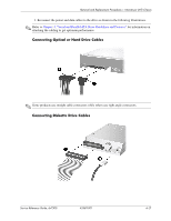
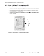
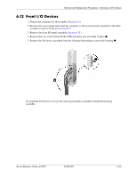
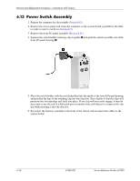
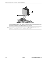
Removal and Replacement Procedures- Microtower (MT) Chassis 6.13 Power Switch Assembly 1. Prepare the computer for disassembly (Section 6.1). 2. Remove the access panel and rotate the computer so the system board is parallel to the table to make it easier to work on (Section 6.3). 3. Remove the front I/O panel assembly (Section 6.11). 4. Squeeze the switch holder retaining clips together 1 and push the switch assembly out of the front I/O panel housing 2. 5. Place the switch holder with the switch installed into the inside of the front I/O panel housing and position the legs of the retaining clip into the clip slots. Press firmly so that the clips will penetrate the slot openings and latch into place. If one clip will not easily engage, it may be necessary to use the end of a ball point pen (or another thin, stiff object) to compress the clip leg while inserting it into the clip slot. 6. Reconnect the housing assembly to the front of the chassis and reconnect the cables to the system board. 6-26 433611-001 Service Reference Guide, dx7300
-
 1
1 -
2
-
3
-
4
-
5
-
6
-
7
-
8
-
9
-
10
-
11
-
12
-
13
-
14
-
15
-
16
-
17
-
18
-
19
-
20
-
21
-
22
-
23
-
24
-
25
-
26
-
27
-
28
-
29
-
30
-
31
-
32
-
33
-
34
-
35
-
36
-
37
-
38
-
39
-
40
-
41
-
42
-
43
-
44
-
45
-
46
-
47
-
48
-
49
-
50
-
51
-
52
-
53
-
54
-
55
-
56
-
57
-
58
-
59
-
60
-
61
-
62
-
63
-
64
-
65
-
66
-
67
-
68
-
69
-
70
-
71
-
72
-
73
-
74
-
75
-
76
-
77
-
78
-
79
-
80
-
81
-
82
-
83
-
84
-
85
-
86
-
87
-
88
-
 89
89 -
 90
90 -
 91
91 -
 92
92 -
 93
93 -
 94
94 -
 95
95 -
 96
96 -
 97
97 -
 98
98 -
 99
99 -
100
-
101
-
102
-
103
-
104
-
105
-
106
-
107
-
108
-
109
-
110
-
111
-
112
-
113
-
114
-
115
-
116
-
117
-
118
-
119
-
120
-
121
-
122
-
123
-
124
-
125
-
126
-
127
-
128
-
129
-
130
-
131
-
132
-
133
-
134
-
135
-
136
-
137
-
138
-
139
-
140
-
141
-
142
-
143
-
144
-
145
-
146
-
147
-
148
-
149
-
150
-
151
-
152
-
153
-
154
-
155
-
156
-
157
-
158
-
159
-
160
-
161
-
162
-
163
-
164
-
165
-
166
-
167
-
168
-
169
-
170
-
171
-
172
-
173
-
174
-
175
-
176
-
177
-
178
-
179
-
180
-
181
-
182
-
183
-
184
-
185
-
186
-
187
-
188
-
189
-
190
-
191
-
192
-
193
-
194
-
195
-
196
-
197
-
198
-
199
-
200
-
201
-
202
-
203
-
204
-
205
-
206
-
207
-
208
-
209
-
210
-
211
-
212
-
213
-
214
-
215
-
216
-
217
-
218
-
219
-
220
-
221
-
222
-
223
-
224
-
225
-
226
-
227
-
228
-
229
-
230
-
231
-
232
-
233
-
234
 |
 |