HP dx7300 HP Compaq dx7300 Business PC Service Reference Guide, 1st Edition - Page 95
Heatsink
 |
View all HP dx7300 manuals
Add to My Manuals
Save this manual to your list of manuals |
Page 95 highlights
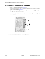
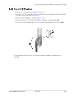
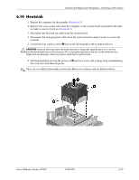
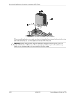
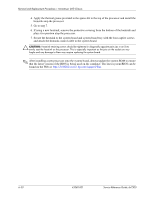
Removal and Replacement Procedures- Microtower (MT) Chassis 6.14 Heatsink 1. Prepare the computer for disassembly (Section 6.1). 2. Remove the access panel and rotate the computer so the system board is parallel to the table to make it easier to work on (Section 6.3). 3. Disconnect the heatsink fan cable from the system board. 4. Disconnect the four-pin power cable from the system board to make it easier to access the heatsink. 5. Loosen the four captive screws 1 that secure the heatsink to the system board tray. Ä CAUTION: Heatsink retaining screws should be removed in diagonally opposite pairs (as in an X) to even the downward forces on the processor. This is especially important as the pins on the socket are very fragile and any damage to them may require replacing the system board. 6. Lift the heatsink from atop the processor 2 and set it on its side to keep from contaminating the work area with thermal grease. ✎ There are two different heatsinks used on the Microtower chassis and are illustrated here. Service Reference Guide, dx7300 433611-001 6-27
-
 1
1 -
2
-
3
-
4
-
5
-
6
-
7
-
8
-
9
-
10
-
11
-
12
-
13
-
14
-
15
-
16
-
17
-
18
-
19
-
20
-
21
-
22
-
23
-
24
-
25
-
26
-
27
-
28
-
29
-
30
-
31
-
32
-
33
-
34
-
35
-
36
-
37
-
38
-
39
-
40
-
41
-
42
-
43
-
44
-
45
-
46
-
47
-
48
-
49
-
50
-
51
-
52
-
53
-
54
-
55
-
56
-
57
-
58
-
59
-
60
-
61
-
62
-
63
-
64
-
65
-
66
-
67
-
68
-
69
-
70
-
71
-
72
-
73
-
74
-
75
-
76
-
77
-
78
-
79
-
80
-
81
-
82
-
83
-
84
-
85
-
86
-
87
-
88
-
89
-
 90
90 -
 91
91 -
 92
92 -
 93
93 -
 94
94 -
 95
95 -
 96
96 -
 97
97 -
 98
98 -
 99
99 -
 100
100 -
101
-
102
-
103
-
104
-
105
-
106
-
107
-
108
-
109
-
110
-
111
-
112
-
113
-
114
-
115
-
116
-
117
-
118
-
119
-
120
-
121
-
122
-
123
-
124
-
125
-
126
-
127
-
128
-
129
-
130
-
131
-
132
-
133
-
134
-
135
-
136
-
137
-
138
-
139
-
140
-
141
-
142
-
143
-
144
-
145
-
146
-
147
-
148
-
149
-
150
-
151
-
152
-
153
-
154
-
155
-
156
-
157
-
158
-
159
-
160
-
161
-
162
-
163
-
164
-
165
-
166
-
167
-
168
-
169
-
170
-
171
-
172
-
173
-
174
-
175
-
176
-
177
-
178
-
179
-
180
-
181
-
182
-
183
-
184
-
185
-
186
-
187
-
188
-
189
-
190
-
191
-
192
-
193
-
194
-
195
-
196
-
197
-
198
-
199
-
200
-
201
-
202
-
203
-
204
-
205
-
206
-
207
-
208
-
209
-
210
-
211
-
212
-
213
-
214
-
215
-
216
-
217
-
218
-
219
-
220
-
221
-
222
-
223
-
224
-
225
-
226
-
227
-
228
-
229
-
230
-
231
-
232
-
233
-
234
 |
 |