HP dx7300 HP Compaq dx7300 Business PC Service Reference Guide, 1st Edition - Page 153
Power Switch Assembly
 |
View all HP dx7300 manuals
Add to My Manuals
Save this manual to your list of manuals |
Page 153 highlights
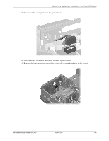
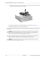
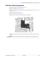
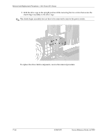
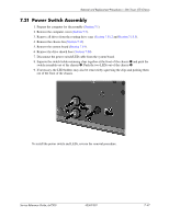
Removal and Replacement Procedures- Slim Tower (ST) Chassis 7.21 Power Switch Assembly 1. Prepare the computer for disassembly (Section 7.1). 2. Remove the computer cover (Section 7.5). 3. Remove all drives from the rotating drive cage (Section 7.11.2 and Section 7.11.3). 4. Remove the chassis fan (Section 7.18). 5. Remove the system board (Section 7.19). 6. Remove the drive ckutch base (Section 7.20). 7. Disconnect the power switch/LED cable from the system board. 8. Squeeze the switch holder retaining clips together at the front of the chassis 1 and push the switch assembly out of the chassis 2. Push the two LEDs out of the chassis 3. 9. If necessary, the LED holders may also be removed by squeezing the clips and pushing them out of the front of the chassis. To install the power switch and LEDs, reverse the removal procedure. Service Reference Guide, dx7300 433611-001 7-47
-
 1
1 -
2
-
3
-
4
-
5
-
6
-
7
-
8
-
9
-
10
-
11
-
12
-
13
-
14
-
15
-
16
-
17
-
18
-
19
-
20
-
21
-
22
-
23
-
24
-
25
-
26
-
27
-
28
-
29
-
30
-
31
-
32
-
33
-
34
-
35
-
36
-
37
-
38
-
39
-
40
-
41
-
42
-
43
-
44
-
45
-
46
-
47
-
48
-
49
-
50
-
51
-
52
-
53
-
54
-
55
-
56
-
57
-
58
-
59
-
60
-
61
-
62
-
63
-
64
-
65
-
66
-
67
-
68
-
69
-
70
-
71
-
72
-
73
-
74
-
75
-
76
-
77
-
78
-
79
-
80
-
81
-
82
-
83
-
84
-
85
-
86
-
87
-
88
-
89
-
90
-
91
-
92
-
93
-
94
-
95
-
96
-
97
-
98
-
99
-
100
-
101
-
102
-
103
-
104
-
105
-
106
-
107
-
108
-
109
-
110
-
111
-
112
-
113
-
114
-
115
-
116
-
117
-
118
-
119
-
120
-
121
-
122
-
123
-
124
-
125
-
126
-
127
-
128
-
129
-
130
-
131
-
132
-
133
-
134
-
135
-
136
-
137
-
138
-
139
-
140
-
141
-
142
-
143
-
144
-
145
-
146
-
147
-
 148
148 -
 149
149 -
 150
150 -
 151
151 -
 152
152 -
 153
153 -
 154
154 -
 155
155 -
 156
156 -
 157
157 -
 158
158 -
159
-
160
-
161
-
162
-
163
-
164
-
165
-
166
-
167
-
168
-
169
-
170
-
171
-
172
-
173
-
174
-
175
-
176
-
177
-
178
-
179
-
180
-
181
-
182
-
183
-
184
-
185
-
186
-
187
-
188
-
189
-
190
-
191
-
192
-
193
-
194
-
195
-
196
-
197
-
198
-
199
-
200
-
201
-
202
-
203
-
204
-
205
-
206
-
207
-
208
-
209
-
210
-
211
-
212
-
213
-
214
-
215
-
216
-
217
-
218
-
219
-
220
-
221
-
222
-
223
-
224
-
225
-
226
-
227
-
228
-
229
-
230
-
231
-
232
-
233
-
234
 |
 |