HP dx7300 HP Compaq dx7300 Business PC Service Reference Guide, 1st Edition - Page 73
Front Bezel
 |
View all HP dx7300 manuals
Add to My Manuals
Save this manual to your list of manuals |
Page 73 highlights
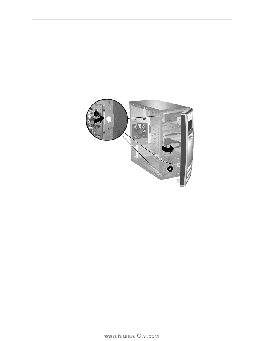
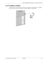
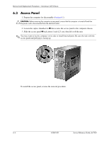
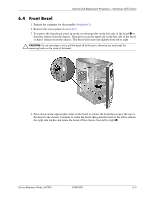
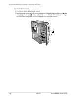
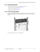
Removal and Replacement Procedures- Microtower (MT) Chassis 6.4 Front Bezel 1. Prepare the computer for disassembly (Section 6.1). 2. Remove the access panel (Section 6.3). 3. To remove the front bezel, press in on the two bottom tabs on the left side of the bezel 1 so that they release from the chassis. Then press in on the upper tab on the left side of the bezel so that it releases from the chassis. The bezel will rotate out slightly from left to right. Ä CAUTION: Do not over-rotate or try to pull the bezel off at this point, otherwise you may break the remaining hooks on the inside of the bezel. 4. Press down on the upper right corner of the bezel to release the hook that secures the top of the bezel to the chassis. Continue to rotate the bezel, then push the bezel to the left to release the right side latches and rotate the bezel off the chassis from left to right 2. Service Reference Guide, dx7300 433611-001 6-5
-
 1
1 -
2
-
3
-
4
-
5
-
6
-
7
-
8
-
9
-
10
-
11
-
12
-
13
-
14
-
15
-
16
-
17
-
18
-
19
-
20
-
21
-
22
-
23
-
24
-
25
-
26
-
27
-
28
-
29
-
30
-
31
-
32
-
33
-
34
-
35
-
36
-
37
-
38
-
39
-
40
-
41
-
42
-
43
-
44
-
45
-
46
-
47
-
48
-
49
-
50
-
51
-
52
-
53
-
54
-
55
-
56
-
57
-
58
-
59
-
60
-
61
-
62
-
63
-
64
-
65
-
66
-
67
-
 68
68 -
 69
69 -
 70
70 -
 71
71 -
 72
72 -
 73
73 -
 74
74 -
 75
75 -
 76
76 -
 77
77 -
 78
78 -
79
-
80
-
81
-
82
-
83
-
84
-
85
-
86
-
87
-
88
-
89
-
90
-
91
-
92
-
93
-
94
-
95
-
96
-
97
-
98
-
99
-
100
-
101
-
102
-
103
-
104
-
105
-
106
-
107
-
108
-
109
-
110
-
111
-
112
-
113
-
114
-
115
-
116
-
117
-
118
-
119
-
120
-
121
-
122
-
123
-
124
-
125
-
126
-
127
-
128
-
129
-
130
-
131
-
132
-
133
-
134
-
135
-
136
-
137
-
138
-
139
-
140
-
141
-
142
-
143
-
144
-
145
-
146
-
147
-
148
-
149
-
150
-
151
-
152
-
153
-
154
-
155
-
156
-
157
-
158
-
159
-
160
-
161
-
162
-
163
-
164
-
165
-
166
-
167
-
168
-
169
-
170
-
171
-
172
-
173
-
174
-
175
-
176
-
177
-
178
-
179
-
180
-
181
-
182
-
183
-
184
-
185
-
186
-
187
-
188
-
189
-
190
-
191
-
192
-
193
-
194
-
195
-
196
-
197
-
198
-
199
-
200
-
201
-
202
-
203
-
204
-
205
-
206
-
207
-
208
-
209
-
210
-
211
-
212
-
213
-
214
-
215
-
216
-
217
-
218
-
219
-
220
-
221
-
222
-
223
-
224
-
225
-
226
-
227
-
228
-
229
-
230
-
231
-
232
-
233
-
234
 |
 |