Hikvision DS-7316HQHI-SH User Manual - Page 16
Power Supply
 |
View all Hikvision DS-7316HQHI-SH manuals
Add to My Manuals
Save this manual to your list of manuals |
Page 16 highlights
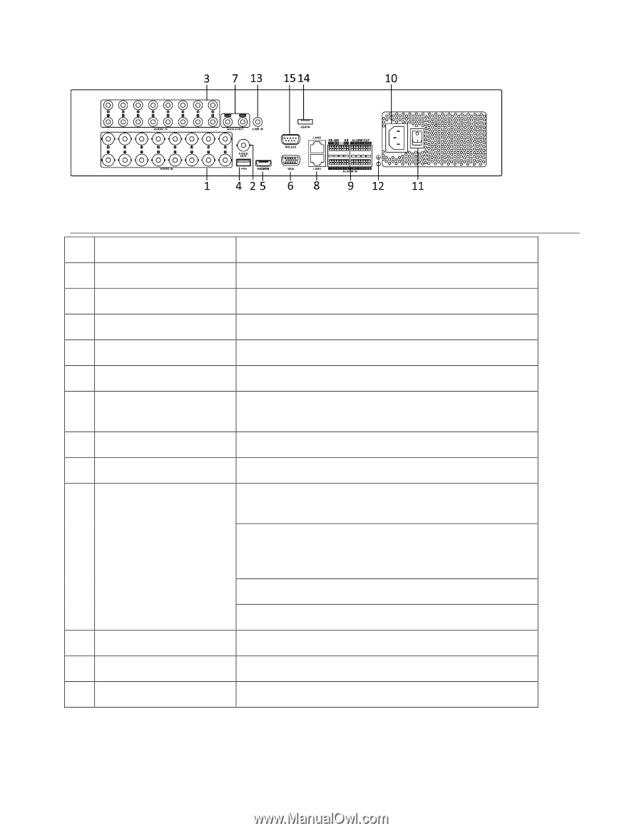
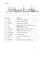
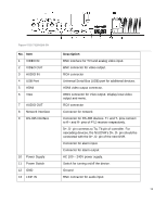
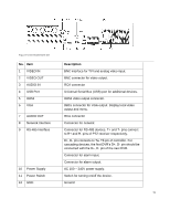
Figure 6 DS-9016HQHI-SH No. Item 1 VIDEO IN 2 VIDEO OUT 3 AUDIO IN 4 USB Port 5 HDMI 6 VGA 7 AUDIO OUT 8 Network Interface 9 RS-485 Interface 10 Power Supply 11 Power Switch 12 GND Description BNC interface for TVI and analog video input. BNC connector for video output. RCA connector Universal Serial Bus (USB) port for additional devices. HDMI video output connector. DB15 connector for VGA output. Display local video output and menu. RCA connector Connector for network Connector for RS-485 devices. T+ and T- pins connect to R+ and R- pins of PTZ receiver respectively. D+, D- pin connects to Ta, Tb pin of controller. For cascading devices, the first DVR's D+, D- pin should be connected with the D+, D- pin of the next DVR. Connector for alarm input. Connector for alarm output. AC 100 ~ 240V power supply. Switch for turning on/off the device. Ground 15
-
 1
1 -
2
-
3
-
4
-
5
-
6
-
7
-
8
-
9
-
10
-
 11
11 -
 12
12 -
 13
13 -
 14
14 -
 15
15 -
 16
16 -
 17
17 -
 18
18 -
 19
19 -
 20
20 -
 21
21 -
22
-
23
-
24
-
25
-
26
-
27
-
28
-
29
-
30
-
31
-
32
-
33
-
34
-
35
-
36
-
37
-
38
-
39
-
40
-
41
-
42
-
43
-
44
-
45
-
46
-
47
-
48
-
49
-
50
-
51
-
52
-
53
-
54
-
55
-
56
-
57
-
58
-
59
-
60
-
61
-
62
-
63
-
64
-
65
-
66
-
67
-
68
-
69
-
70
-
71
-
72
-
73
-
74
-
75
-
76
-
77
-
78
-
79
-
80
-
81
-
82
-
83
-
84
-
85
-
86
-
87
-
88
-
89
-
90
-
91
-
92
-
93
-
94
-
95
-
96
-
97
-
98
-
99
-
100
-
101
-
102
-
103
-
104
-
105
-
106
-
107
-
108
-
109
-
110
-
111
-
112
-
113
-
114
-
115
-
116
-
117
-
118
-
119
-
120
-
121
-
122
-
123
-
124
-
125
-
126
-
127
-
128
-
129
-
130
-
131
-
132
-
133
-
134
-
135
-
136
-
137
-
138
-
139
-
140
-
141
-
142
-
143
 |
 |