IBM 8840 Hardware Maintenance Manual - Page 58
power-cord
 |
UPC - 000435863799
View all IBM 8840 manuals
Add to My Manuals
Save this manual to your list of manuals |
Page 58 highlights
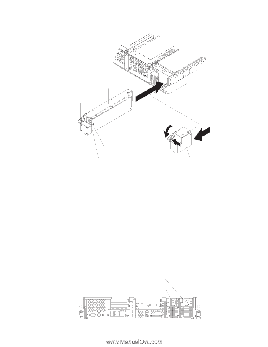
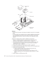
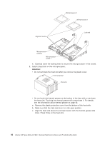
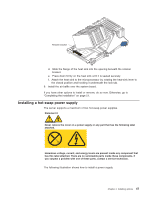
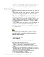
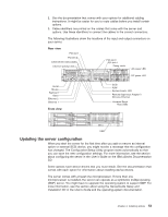
Power supply Handle (open position) AC power LED (green) DC power LED (green) Power-supply blank (some models) Complete the following steps to install a power supply: 1. Read the "Installation guidelines" on page 23.and the safety information beginning on page Appendix B, "Safety information," on page 117. 2. (Some models) Remove the power-supply blank from the empty power-supply bay by pinching the side clip and pulling the power-supply blank from the bay. Save the power-supply blank in case you remove the power supply at a later time. Attention: During normal operation, each power-supply bay must have either a power supply or power-supply blank installed for proper cooling. 3. Install the power supply in the bay: a. Move the handle on the power supply into the open position, pinch the side-clip, and slide the power supply into the chassis. b. Gently close the handle to seat the power supply in the bay. 4. Connect the power cord for the new power supply to the power-cord connector on the power supply. The following illustration shows the power-supply connectors on the back of the server. Power supply 2 power cord connector Power supply 1 power cord connector TX/RX LINK TX/RX LINK 48 xSeries 346 Types 8840 and 1880: Hardware Maintenance Manual and Troubleshooting Guide
-
 1
1 -
2
-
3
-
4
-
5
-
6
-
7
-
8
-
9
-
10
-
11
-
12
-
13
-
14
-
15
-
16
-
17
-
18
-
19
-
20
-
21
-
22
-
23
-
24
-
25
-
26
-
27
-
28
-
29
-
30
-
31
-
32
-
33
-
34
-
35
-
36
-
37
-
38
-
39
-
40
-
41
-
42
-
43
-
44
-
45
-
46
-
47
-
48
-
49
-
50
-
51
-
52
-
 53
53 -
 54
54 -
 55
55 -
 56
56 -
 57
57 -
 58
58 -
 59
59 -
 60
60 -
 61
61 -
 62
62 -
 63
63 -
64
-
65
-
66
-
67
-
68
-
69
-
70
-
71
-
72
-
73
-
74
-
75
-
76
-
77
-
78
-
79
-
80
-
81
-
82
-
83
-
84
-
85
-
86
-
87
-
88
-
89
-
90
-
91
-
92
-
93
-
94
-
95
-
96
-
97
-
98
-
99
-
100
-
101
-
102
-
103
-
104
-
105
-
106
-
107
-
108
-
109
-
110
-
111
-
112
-
113
-
114
-
115
-
116
-
117
-
118
-
119
-
120
-
121
-
122
-
123
-
124
-
125
-
126
-
127
-
128
-
129
-
130
-
131
-
132
-
133
-
134
-
135
-
136
-
137
-
138
-
139
-
140
-
141
-
142
-
143
-
144
-
145
-
146
-
147
-
148
-
149
-
150
-
151
-
152
-
153
-
154
-
155
-
156
-
157
-
158
-
159
-
160
-
161
-
162
-
163
-
164
-
165
-
166
-
167
-
168
-
169
-
170
-
171
-
172
-
173
-
174
-
175
-
176
 |
 |