IBM SAN16B-2 User Guide - Page 24
Supported, connectivity, Switch, characteristics, SAN16B-2, switch - totalstorage power
 |
UPC - 000435819895
View all IBM SAN16B-2 manuals
Add to My Manuals
Save this manual to your list of manuals |
Page 24 highlights
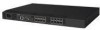
Supported connectivity Specific details on supported operating systems, servers, and devices, storage products attachability, SAN connectivity products, and configuration options are available at the following web site: http://www.ibm.com/totalstorage/san/b-type. The switch supports Fibre Channel connectivity for the following: Servers v IBM eServer™ pSeries® and selected RS/6000® servers v IBM eServer iSeries™ and selected AS/400® servers v IBM eServer xSeries® and selected Netfinity® servers v Other Intel-based servers with Linux™ and Windows® 2000 and Windows 2003 Server v Selected Sun and HP servers Storage Systems v IBM TotalStorage DS4000 Series v IBM TotalStorage DS6000 Series v IBM TotalStorage DS8000 Series v IBM TotalStorage FAStT Family of Storage Servers v IBM TotalStorage Enterprise Storage Server® (ESS) v IBM TotalStorage SAN Volume Controller v IBM TotalStorage 3580, 3588, 3590 and 3592 Tape Drives v IBM TotalStorage 3494, 3582, 3583, and 3584 Tape Libraries v IBM TotalStorage 3581 Tape Autoloader v IBM TotalStorage 3584 High Availability Frame Model HA1 v Other selected storage systems Switch characteristics The following sections describe the physical characteristics of the switch. Port side of the SAN16B-2 switch Figure 1 on page 3 shows the port side of the switch. The serial port, Ethernet port, and the Fibre Channel ports are all located on this side of the switch. All LEDs are also located on the port side of the switch. These LEDs display the system status, power status, port status, and port speed. See "Interpreting LED activity" on page 21 for a complete description of the locations and interpretations of these LEDs. The switch enclosure has forced-air cooling, with the fans pushing the air from the non-port side of the chassis through the enclosure, and exhausting through the holes on the port side. Three dual speed fans provide the cooling for the switch. 2 SAN16B-2 Installation, Service, and User's Guide
-
 1
1 -
2
-
3
-
4
-
5
-
6
-
7
-
8
-
9
-
10
-
11
-
12
-
13
-
14
-
15
-
16
-
17
-
18
-
 19
19 -
 20
20 -
 21
21 -
 22
22 -
 23
23 -
 24
24 -
 25
25 -
 26
26 -
 27
27 -
 28
28 -
 29
29 -
30
-
31
-
32
-
33
-
34
-
35
-
36
-
37
-
38
-
39
-
40
-
41
-
42
-
43
-
44
-
45
-
46
-
47
-
48
-
49
-
50
-
51
-
52
-
53
-
54
-
55
-
56
-
57
-
58
-
59
-
60
-
61
-
62
-
63
-
64
-
65
-
66
-
67
-
68
-
69
-
70
-
71
-
72
-
73
-
74
-
75
-
76
-
77
-
78
-
79
-
80
-
81
-
82
-
83
-
84
-
85
-
86
-
87
-
88
-
89
-
90
-
91
-
92
-
93
 |
 |
