IBM SAN16B-2 User Guide - Page 43
Operating, SAN16B-2
 |
UPC - 000435819895
View all IBM SAN16B-2 manuals
Add to My Manuals
Save this manual to your list of manuals |
Page 43 highlights
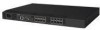
Chapter 3. Operating the SAN16B-2 This chapter provides the following information: v "Powering the SAN16B-2 on and off" v "Interpreting LED activity" v "POST and boot specifications" on page 25 v "Interpreting POST results" on page 26 Powering the SAN16B-2 on and off See Chapter 2, "Installing and configuring the SAN16B-2," on page 7 for initial setup instructions before powering the switch on for the first time. Once the switch has been properly configured, follow these instructions to power the switch on and off at other times. To power on the switch, connect the power cable to the ac receptacle on the switch and to a power source. The switch runs POST by default each time it is powered on, reset, or rebooted, and requires a minimum of 3 minutes to run. To end the flow of power to the switch, remove the power cord from the power source. Interpreting LED activity System activity and status can be determined through the activity of the LEDs on the switch. All the switch's LEDs are located on the port side of the switch. There are three possible LED states: no light, a steady light, and a flashing light. The steady lights and flashing lights can be green or amber. Sometimes the LEDs flash either of these colors during boot, POST, or other diagnostic tests. This is normal and does not indicate a problem unless all boot processes and diagnostic tests are complete, and the LEDs continue to indicate a problem status. LED location The LEDs are located on the port side of the switch (see Figure 9 on page 22). They include: v Power Status 8 (green only) to indicate a valid power supply to the system v System Status 9 (green/amber) to indicate the current system status v Ethernet Link 11 to indicate an active Ethernet connection v Ethernet Speed 10 to indicate the Ethernet speed v Port Status 7 (green/amber), located in pairs below each pair of Fibre Channel ports (left LED of each pair) v Port Speed 6 (green/amber), located in pairs below each pair of Fibre Channel ports (right LED of each pair) Note: The pairs of port LEDs for all 16 ports are arrayed below the lower row of ports. The pairs of port LEDs are located in the array in the same relative positions as the ports. The port number of the associated Fibre Channel port appears between the Port Status and Port Speed LEDs. © Copyright IBM Corp. 2005 21
-
 1
1 -
2
-
3
-
4
-
5
-
6
-
7
-
8
-
9
-
10
-
11
-
12
-
13
-
14
-
15
-
16
-
17
-
18
-
19
-
20
-
21
-
22
-
23
-
24
-
25
-
26
-
27
-
28
-
29
-
30
-
31
-
32
-
33
-
34
-
35
-
36
-
37
-
 38
38 -
 39
39 -
 40
40 -
 41
41 -
 42
42 -
 43
43 -
 44
44 -
 45
45 -
 46
46 -
 47
47 -
 48
48 -
49
-
50
-
51
-
52
-
53
-
54
-
55
-
56
-
57
-
58
-
59
-
60
-
61
-
62
-
63
-
64
-
65
-
66
-
67
-
68
-
69
-
70
-
71
-
72
-
73
-
74
-
75
-
76
-
77
-
78
-
79
-
80
-
81
-
82
-
83
-
84
-
85
-
86
-
87
-
88
-
89
-
90
-
91
-
92
-
93
 |
 |
