Icom IC-7000 Instruction Manual - Page 31
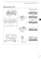
Connections for CW - microphone
 |
View all Icom IC-7000 manuals
Add to My Manuals
Save this manual to your list of manuals |
Page 31 highlights
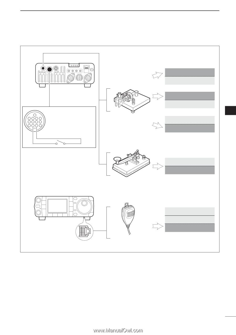
■ Connections for CW [KEY] Rear panel [ACC] 13 9 10 11 12 5678 1234 For no break-in operation: Connect an external switch such as a foot switch; or use the RTTY SEND terminal for all bands. (See p. 23) 2 INSTALLATION AND CONNECTIONS Paddle Straight key Keyer Set mode (p. 49) Keyer Set mode setting Paddle polarity Normal Keyer Type ELEC-KEY Normal Paddle polarity Reverse Keyer Type ELEC-KEY Reverse 2 Paddle polarity Normal Keyer Type BUG-KEY Bug Paddle polarity Keyer Type Normal Straight [MICROPHONE] See p. 50 for connection details: Paddle operation from [MIC] connector. Microphone (HM-103) Paddle polarity Normal Keyer Type ELEC-KEY MIC U/D keyer (HM-103) ON 22
-
 1
1 -
2
-
3
-
4
-
5
-
6
-
7
-
8
-
9
-
10
-
11
-
12
-
13
-
14
-
15
-
16
-
17
-
18
-
19
-
20
-
21
-
22
-
23
-
24
-
25
-
 26
26 -
 27
27 -
 28
28 -
 29
29 -
 30
30 -
 31
31 -
 32
32 -
 33
33 -
 34
34 -
 35
35 -
 36
36 -
37
-
38
-
39
-
40
-
41
-
42
-
43
-
44
-
45
-
46
-
47
-
48
-
49
-
50
-
51
-
52
-
53
-
54
-
55
-
56
-
57
-
58
-
59
-
60
-
61
-
62
-
63
-
64
-
65
-
66
-
67
-
68
-
69
-
70
-
71
-
72
-
73
-
74
-
75
-
76
-
77
-
78
-
79
-
80
-
81
-
82
-
83
-
84
-
85
-
86
-
87
-
88
-
89
-
90
-
91
-
92
-
93
-
94
-
95
-
96
-
97
-
98
-
99
-
100
-
101
-
102
-
103
-
104
-
105
-
106
-
107
-
108
-
109
-
110
-
111
-
112
-
113
-
114
-
115
-
116
-
117
-
118
-
119
-
120
-
121
-
122
-
123
-
124
-
125
-
126
-
127
-
128
-
129
-
130
-
131
-
132
-
133
-
134
-
135
-
136
-
137
-
138
-
139
-
140
-
141
-
142
-
143
-
144
-
145
-
146
-
147
-
148
-
149
-
150
-
151
-
152
-
153
-
154
-
155
-
156
-
157
-
158
-
159
-
160
-
161
-
162
-
163
-
164
-
165
-
166
 |
 |
22
2
INSTALLATION AND CONNECTIONS
2
Rear panel
Paddle
[KEY]
[MICROPHONE]
Straight key
Microphone (HM-103)
Keyer Set mode setting
Keyer Set mode (p. 49)
4
8
12
[ACC]
1
2
3
7
6
5
9
10
11
13
For no break-in operation:
Connect an external switch
such as a foot switch; or use
the RTTY SEND terminal for
all bands. (See p. 23)
See p. 50 for connection details:
Paddle operation from [MIC]
connector
.
Normal
Reverse
Bug
Paddle polarity
Normal
MIC U/D keyer (HM-103)
ON
Keyer Type
ELEC-KEY
Paddle polarity
Normal
Keyer Type
Straight
Paddle polarity
Normal
Keyer Type
ELEC-KEY
Paddle polarity
Reverse
Keyer Type
ELEC-KEY
Paddle polarity
Normal
Keyer Type
BUG-KEY
■
Connections for CW