Icom M604A Instruction Manual - Page 58
■ Mounting the transceiver, Using the supplied mounting bracket
 |
View all Icom M604A manuals
Add to My Manuals
Save this manual to your list of manuals |
Page 58 highlights
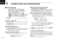
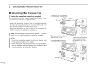
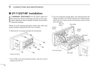
9 CONNECTIONS AND MAINTENANCE ■ Mounting the transceiver D Using the supplied mounting bracket The universal mounting bracket supplied with your transceiver allows overhead or upright mounting. • Mount the transceiver securely with the 4 supplied screws (5 × 20 mm) to a surface which is more than 10 mm (0.4 in) thick and can support more than 5 kg (11 lb). • Mount the transceiver so that the face of the transceiver is at 90° to your line of sight when operating it. KEEP the transceiver and microphone at least 1 m (3.3 ft) away from the vessel's magnetic navigation compass. NOTE: • Check the installation angle; the function display may not be easy-to-read at some angles. • If the transceiver mounting place has strong vibration, use the supplied sponges between the transceiver and mounting bracket to reduce the vibration. • OVERHEAD MOUNTING Sponge* *Sponges reduce the vibration. See NOTE to the left. • UPRIGHT MOUNTING These bolts are shown as only mounting example. Not supplied with accessories. Sponge* 52
-
 1
1 -
2
-
3
-
4
-
5
-
6
-
7
-
8
-
9
-
10
-
11
-
12
-
13
-
14
-
15
-
16
-
17
-
18
-
19
-
20
-
21
-
22
-
23
-
24
-
25
-
26
-
27
-
28
-
29
-
30
-
31
-
32
-
33
-
34
-
35
-
36
-
37
-
38
-
39
-
40
-
41
-
42
-
43
-
44
-
45
-
46
-
47
-
48
-
49
-
50
-
51
-
52
-
 53
53 -
 54
54 -
 55
55 -
 56
56 -
 57
57 -
 58
58 -
 59
59 -
 60
60 -
 61
61 -
 62
62 -
 63
63 -
64
-
65
-
66
-
67
-
68
 |
 |
