Icom M604A Instruction Manual - Page 62
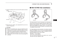
into the [COMMAND MIC-1] or [COMMAND MIC-2], HM-157/HM162 installation Continued
 |
View all Icom M604A manuals
Add to My Manuals
Save this manual to your list of manuals |
Page 62 highlights
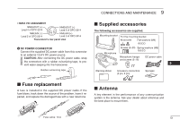
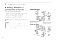
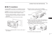
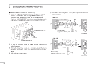
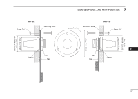
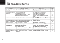
9 CONNECTIONS AND MAINTENANCE ■ HM-157/HM162 installation (Continued) q Insert the supplied cable (or HM-157 without the cable) into the [COMMAND MIC-1] or [COMMAND MIC-2] connector and tighten the cable nut as shown below. • Up to two COMMANDMIC™s can be connected simultaneously. • The HM-157 and HM-162 can be connected at the same time. t Install the mounting base using the supplied screws as shown below. • HM-157 Mounting base Nut [COMMAND MIC-2] [COMMAND MIC-1] w To use the supplied cable as a wall socket, perform the following steps. e Using the mounting base as a template, carefully mark the holes where the cable and three screws will be fastened. r Drill holes at these marks. Gasket Screw holes Cap (approx. 2 (d) mm; 3 32″) Completed • HM-162 Mounting base Nut Gasket Screw holes (approx. 2 (d) mm; 3 32″) Cap Completed 56
-
 1
1 -
2
-
3
-
4
-
5
-
6
-
7
-
8
-
9
-
10
-
11
-
12
-
13
-
14
-
15
-
16
-
17
-
18
-
19
-
20
-
21
-
22
-
23
-
24
-
25
-
26
-
27
-
28
-
29
-
30
-
31
-
32
-
33
-
34
-
35
-
36
-
37
-
38
-
39
-
40
-
41
-
42
-
43
-
44
-
45
-
46
-
47
-
48
-
49
-
50
-
51
-
52
-
53
-
54
-
55
-
56
-
 57
57 -
 58
58 -
 59
59 -
 60
60 -
 61
61 -
 62
62 -
 63
63 -
 64
64 -
 65
65 -
 66
66 -
 67
67 -
68
 |
 |
