Icom M604A Instruction Manual - Page 61
■ HM-157/HM-162 installation
 |
View all Icom M604A manuals
Add to My Manuals
Save this manual to your list of manuals |
Page 61 highlights
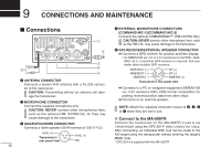
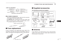
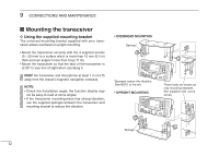
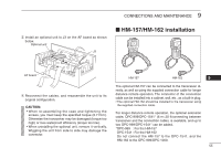
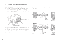
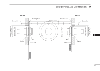
9 CONNECTIONS AND MAINTENANCE e Install an optional unit to J3 on the AF board as shown below. Optional unit J3 ■ HM-157/HM-162 installation AF board r Reconnect the cables, and reassemble the unit to its original configuration. CAUTION: • When re-assembling the case and tightening the screws, you must keep the specified torque (0.7 N.m). Otherwise the transceiver may be damaged (torque too high) or lose waterproof efficiency (torque too low). • When unistalling the optional unit, remove it vertically. Wiggling the unit from side to side may damage the connector. HM-157 HM-162 9 The optional HM-157 can be connected to the transceiver directly, as well as using the supplied connection cable for longer distance remote operation. The connector of the connection cable can be installed into a cabinet, wall, etc., as a built-in plug. • The optional HM-162 should be installed to the transceiver using the supplied connection cable. For longer distance remote operation, the optional extension cable, OPC-999/OPC-1541* (6 m; 20 ft/connecting between transceiver and the connection cable), is available, and up to two OPC-999/OPC-1541* can be added. *OPC-999 : For the HM-157 OPC-1541 : For the HM-162 Do not connect the HM-157 to the OPC-1541, and the HM-162 to the OPC-999/OPC-1000. 55
-
 1
1 -
2
-
3
-
4
-
5
-
6
-
7
-
8
-
9
-
10
-
11
-
12
-
13
-
14
-
15
-
16
-
17
-
18
-
19
-
20
-
21
-
22
-
23
-
24
-
25
-
26
-
27
-
28
-
29
-
30
-
31
-
32
-
33
-
34
-
35
-
36
-
37
-
38
-
39
-
40
-
41
-
42
-
43
-
44
-
45
-
46
-
47
-
48
-
49
-
50
-
51
-
52
-
53
-
54
-
55
-
 56
56 -
 57
57 -
 58
58 -
 59
59 -
 60
60 -
 61
61 -
 62
62 -
 63
63 -
 64
64 -
 65
65 -
 66
66 -
67
-
68
 |
 |
