Icom M604A Instruction Manual - Page 60
■ UT-112/UT-98* installation
 |
View all Icom M604A manuals
Add to My Manuals
Save this manual to your list of manuals |
Page 60 highlights
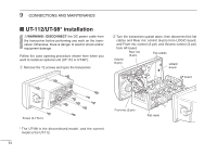
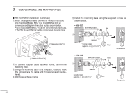
9 CONNECTIONS AND MAINTENANCE ■ UT-112/UT-98* installation RWARNING!: DISCONNECT the DC power cable from the transceiver before performing any work on the transceiver. Otherwise, there is danger of electric shock and/or equipment damage. Follow the case opening procedure shown here when you want to install an optional unit (UT-112 or UT-98*). q Remove the 12 screws and open the transceiver. w Turn the transceiver upside down, then disconnect the flat cables and Rear mic control (6-pin) from LOGIC board, and Front mic control (2-pin) and Volume control (3-pin) from AF board. Rear mic (6-pin) Flat cables Volume (3-pin) LOGIC board AF board Torque (0.7 N.m) * The UT-98 is the discontinued model, and the current model is the UT-112. 54 Front mic (2-pin) Flat cable
-
 1
1 -
2
-
3
-
4
-
5
-
6
-
7
-
8
-
9
-
10
-
11
-
12
-
13
-
14
-
15
-
16
-
17
-
18
-
19
-
20
-
21
-
22
-
23
-
24
-
25
-
26
-
27
-
28
-
29
-
30
-
31
-
32
-
33
-
34
-
35
-
36
-
37
-
38
-
39
-
40
-
41
-
42
-
43
-
44
-
45
-
46
-
47
-
48
-
49
-
50
-
51
-
52
-
53
-
54
-
 55
55 -
 56
56 -
 57
57 -
 58
58 -
 59
59 -
 60
60 -
 61
61 -
 62
62 -
 63
63 -
 64
64 -
 65
65 -
66
-
67
-
68
 |
 |
