Intel D845HV Product Specification - Page 45

Technical Reference

Page 45 highlights

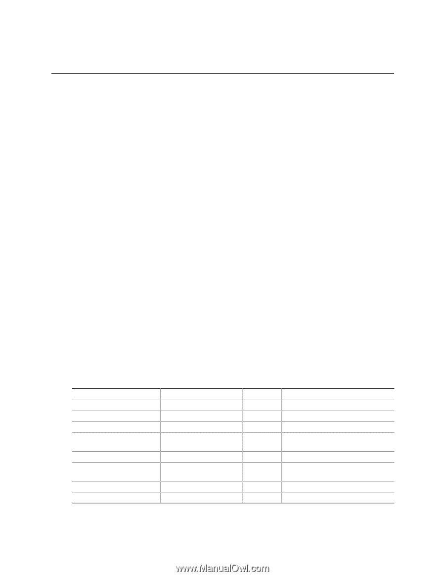
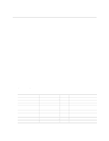
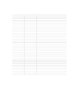
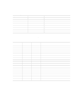
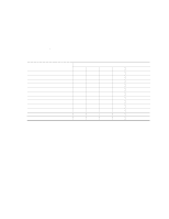
2 Technical Reference What This Chapter Contains 2.1 Introduction...45 2.2 Memory Map ...45 2.3 I/O Map ...46 2.4 DMA Channels ...48 2.5 PCI Configuration Space Map 48 2.6 Interrupts ...49 2.7 PCI Interrupt Routing Map 49 2.8 Connectors ...51 2.9 Jumper Blocks...72 2.10 Mechanical Considerations 74 2.11 Electrical Considerations 78 2.12 Thermal Considerations 81 2.13 Reliability ...83 2.14 Environmental ...83 2.15 Regulatory Compliance 84 2.1 Introduction Sections 2.2 - 2.6 contain several standalone tables. Table 12 describes the system memory map, Table 13 shows the I/O map, Table 14 lists the DMA channels, Table 15 defines the PCI configuration space map, and Table 16 describes the interrupts. The remaining sections in this chapter are introduced by text found with their respective section headings. 2.2 Memory Map Table 12. System Memory Map Address Range (decimal) 1024 K - 3145728 K 960 K - 1024 K 896 K - 960 K 800 K - 896 K Address Range (hex) 100000 - BFFFFFFF F0000 - FFFFF E0000 - EFFFF C8000 - DFFFF 640 K - 800 K 639 K - 640 K A0000 - C7FFF 9FC00 - 9FFFF 512 K - 639 K 0 K - 512 K 80000 - 9FBFF 00000 - 7FFFF Size 3071 MB 64 KB 64 KB 96 KB 160 KB 1 KB 127 KB 512 KB Description Extended memory Runtime BIOS Reserved Available high DOS memory (open to the PCI bus) Video memory and BIOS Extended BIOS data (movable by memory manager software) Extended conventional memory Conventional memory 45

  • 1
  • 2
  • 3
  • 4
  • 5
  • 6
  • 7
  • 8
  • 9
  • 10
  • 11
  • 12
  • 13
  • 14
  • 15
  • 16
  • 17
  • 18
  • 19
  • 20
  • 21
  • 22
  • 23
  • 24
  • 25
  • 26
  • 27
  • 28
  • 29
  • 30
  • 31
  • 32
  • 33
  • 34
  • 35
  • 36
  • 37
  • 38
  • 39
  • 40
  • 41
  • 42
  • 43
  • 44
  • 45
  • 46
  • 47
  • 48
  • 49
  • 50
  • 51
  • 52
  • 53
  • 54
  • 55
  • 56
  • 57
  • 58
  • 59
  • 60
  • 61
  • 62
  • 63
  • 64
  • 65
  • 66
  • 67
  • 68
  • 69
  • 70
  • 71
  • 72
  • 73
  • 74
  • 75
  • 76
  • 77
  • 78
  • 79
  • 80
  • 81
  • 82
  • 83
  • 84
  • 85
  • 86
  • 87
  • 88
  • 89
  • 90
  • 91
  • 92
  • 93
  • 94
  • 95
  • 96
  • 97
  • 98
  • 99
  • 100
  • 101
  • 102
  • 103
  • 104
  • 105
  • 106
  • 107
  • 108
  • 109
  • 110
  • 111
  • 112
  • 113
  • 114
  • 115
  • 116
  • 117
  • 118
  • 119
  • 120
  • 121
  • 122
  • 123
  • 124
  • 125
  • 126
  • 127
  • 128

45
2 Technical Reference
What This Chapter Contains
2.1
Introduction
.................................................................................................................
45
2.2
Memory Map
..............................................................................................................
45
2.3
I/O Map
.....................................................................................................................
46
2.4
DMA Channels
...........................................................................................................
48
2.5
PCI Configuration Space Map
....................................................................................
48
2.6
Interrupts
....................................................................................................................
49
2.7
PCI Interrupt Routing Map
..........................................................................................
49
2.8
Connectors
.................................................................................................................
51
2.9
Jumper Blocks
............................................................................................................
72
2.10
Mechanical Considerations
.........................................................................................
74
2.11
Electrical Considerations
............................................................................................
78
2.12
Thermal Considerations
..............................................................................................
81
2.13
Reliability
....................................................................................................................
83
2.14
Environmental
............................................................................................................
83
2.15
Regulatory Compliance
..............................................................................................
84
2.1 Introduction
Sections 2.2 - 2.6 contain several standalone tables.
Table 12 describes the system memory map,
Table 13 shows the I/O map, Table 14 lists the DMA channels, Table 15 defines the PCI
configuration space map, and Table 16 describes the interrupts.
The remaining sections in this
chapter are introduced by text found with their respective section headings.
2.2 Memory Map
Table 12.
System Memory Map
Address Range (decimal)
Address Range (hex)
Size
Description
1024 K - 3145728 K
100000 - BFFFFFFF
3071 MB
Extended memory
960 K - 1024 K
F0000 - FFFFF
64 KB
Runtime BIOS
896 K - 960 K
E0000 - EFFFF
64 KB
Reserved
800 K - 896 K
C8000 - DFFFF
96 KB
Available high DOS memory (open
to the PCI bus)
640 K - 800 K
A0000 - C7FFF
160 KB
Video memory and BIOS
639 K - 640 K
9FC00 - 9FFFF
1 KB
Extended BIOS data (movable by
memory manager software)
512 K - 639 K
80000 - 9FBFF
127 KB
Extended conventional memory
0 K - 512 K
00000 - 7FFFF
512 KB
Conventional memory