Intel D845HV Product Specification - Page 67
Table 39., PCI IDE Connectors, Table 40., SCSI LED Connector Optional
 |
View all Intel D845HV manuals
Add to My Manuals
Save this manual to your list of manuals |
Page 67 highlights
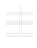
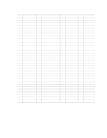
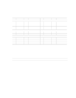
Technical Reference Table 39. PCI IDE Connectors Pin Signal Name Pin Signal Name 1 Reset IDE 2 Ground 3 Data 7 4 Data 8 5 Data 6 6 Data 9 7 Data 5 8 Data 10 9 Data 4 10 Data 11 11 Data 3 12 Data 12 13 Data 2 14 Data 13 15 Data 1 16 Data 14 17 Data 0 18 Data 15 19 Ground 20 Key 21 DDRQ0 [DDRQ1] 22 Ground 23 I/O Write# 24 Ground 25 I/O Read# 26 Ground 27 IOCHRDY 28 P_ALE (Cable Select pull-up) 29 DDACK0# [DDACK1#] 30 Ground 31 IRQ 14 [IRQ 15] 32 Reserved 33 DAG1 (Address 1) 34 GPIO_DMA66_Detect_Pri (GPIO_DMA66_Detect_Sec) 35 DAG0 (Address 0) 36 DAG2 (Address 2) 37 Chip Select 1P# [Chip Select 1S#] 38 Chip Select 3P# [Chip Select 3S#] 39 Activity# 40 Ground Signal names in brackets ([ ]) are for the secondary IDE connector. Table 40. SCSI LED Connector (Optional) Pin Signal Name 1 SCSI_ACT# 2 No connect 67
-
 1
1 -
2
-
3
-
4
-
5
-
6
-
7
-
8
-
9
-
10
-
11
-
12
-
13
-
14
-
15
-
16
-
17
-
18
-
19
-
20
-
21
-
22
-
23
-
24
-
25
-
26
-
27
-
28
-
29
-
30
-
31
-
32
-
33
-
34
-
35
-
36
-
37
-
38
-
39
-
40
-
41
-
42
-
43
-
44
-
45
-
46
-
47
-
48
-
49
-
50
-
51
-
52
-
53
-
54
-
55
-
56
-
57
-
58
-
59
-
60
-
61
-
 62
62 -
 63
63 -
 64
64 -
 65
65 -
 66
66 -
 67
67 -
 68
68 -
 69
69 -
 70
70 -
 71
71 -
 72
72 -
73
-
74
-
75
-
76
-
77
-
78
-
79
-
80
-
81
-
82
-
83
-
84
-
85
-
86
-
87
-
88
-
89
-
90
-
91
-
92
-
93
-
94
-
95
-
96
-
97
-
98
-
99
-
100
-
101
-
102
-
103
-
104
-
105
-
106
-
107
-
108
-
109
-
110
-
111
-
112
-
113
-
114
-
115
-
116
-
117
-
118
-
119
-
120
-
121
-
122
-
123
-
124
-
125
-
126
-
127
-
128
 |
 |