Intel S975XBX2 Product Specification - Page 18
System Memory
 |
UPC - 735858186506
View all Intel S975XBX2 manuals
Add to My Manuals
Save this manual to your list of manuals |
Page 18 highlights
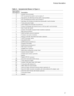
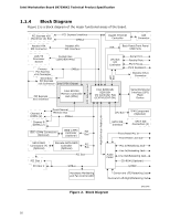
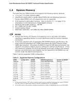
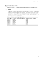
Intel Workstation Board S975XBX2 Technical Product Specification 1.4 System Memory The board has four DIMM sockets and supports the following memory features: • 1.8 V and 1.9 V DDR2 SDRAM DIMMs • Unbuffered, single-sided or double-sided DIMMs with the following restriction: Double-sided DIMMS with x16 organization are not supported. • 8 GB maximum total system memory. Refer to Section 2.1.1 on page 47 for information on the total amount of addressable memory. • Minimum total system memory: 128 MB • ECC DIMMs and non-ECC DIMMs • Serial Presence Detect • DDR2 800, DDR2 667, and DDR2 533 MHz SDRAM DIMMs NOTES • Remove the Primary PCI Express x16 (electrical x16 or x8) video card before installing or upgrading memory to avoid interference with the memory retention mechanism. • To be fully compliant with all applicable DDR SDRAM memory specifications, the board should be populated with DIMMs that support the Serial Presence Detect (SPD) data structure. This allows the BIOS to read the SPD data and program the chipset to accurately configure memory settings for optimum performance. If nonSPD memory is installed, the BIOS will attempt to correctly configure the memory settings, but performance and reliability may be impacted or the DIMMs may not function under the determined frequency. Table 4 lists the supported DIMM configurations. Table 4. Supported Memory Configurations DIMM Capacity 128 MB 256 MB 256 MB 512 MB 512 MB 512 MB 1024 MB 1024 MB 2048 MB Configuration (Note 1) SS SS SS DS SS SS DS SS DS SDRAM Density 256 Mbit 256 Mbit 512 Mbit 256 Mbit 512 Mbit 1 Gbit 512 Mbit 1 Gbit 1 Gbit SDRAM Organization Front-side/Back-side 16 M x 16/empty 32 M x 8/empty 32 M x 16/empty 32 M x 8/32 M x 8 64 M x 8/empty 64 M x 16/empty 64 M x 8/64 M x 8 128 M x 8/empty 128 M x 8/128 M x 8 Number of SDRAM Devices (Note 2) 4 [5] 8 [9] 4 [5] 16 [18] 8 [9] 4 [5] 16 [18] 8 [9] 16 [18] Notes: 1. In the second column, "DS" refers to double-sided memory modules (containing two rows of SDRAM) and "SS" refers to single-sided memory modules (containing one row of SDRAM). 2. In the fifth column, the number in brackets specifies the number of SDRAM devices on an ECC DIMM. 18
-
 1
1 -
2
-
3
-
4
-
5
-
6
-
7
-
8
-
9
-
10
-
11
-
12
-
 13
13 -
 14
14 -
 15
15 -
 16
16 -
 17
17 -
 18
18 -
 19
19 -
 20
20 -
 21
21 -
 22
22 -
 23
23 -
24
-
25
-
26
-
27
-
28
-
29
-
30
-
31
-
32
-
33
-
34
-
35
-
36
-
37
-
38
-
39
-
40
-
41
-
42
-
43
-
44
-
45
-
46
-
47
-
48
-
49
-
50
-
51
-
52
-
53
-
54
-
55
-
56
-
57
-
58
-
59
-
60
-
61
-
62
-
63
-
64
-
65
-
66
-
67
-
68
-
69
-
70
-
71
-
72
-
73
-
74
-
75
-
76
-
77
-
78
-
79
-
80
-
81
-
82
-
83
-
84
-
85
-
86
-
87
-
88
-
89
-
90
-
91
-
92
-
93
-
94
-
95
-
96
-
97
-
98
-
99
-
100
-
101
-
102
 |
 |