Intel S975XBX2 Product Specification - Page 26
Real-Time Clock, CMOS SRAM, and Battery
 |
UPC - 735858186506
View all Intel S975XBX2 manuals
Add to My Manuals
Save this manual to your list of manuals |
Page 26 highlights
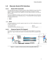
Intel Workstation Board S975XBX2 Technical Product Specification Native mode is the preferred mode for configurations using the Microsoft Windows* XP and Microsoft Windows 2000 operating systems. NOTE Many Serial ATA drives use new low-voltage power connectors and require adaptors or power supplies equipped with low-voltage power connectors. For more information, see: http://www.serialata.org/ For information about The location of the Serial ATA IDE connectors on the S975XBX2 board Refer to Figure 16, page 56 1.5.2.3 Serial ATA RAID The ICH7-R supports the following RAID (Redundant Array of Independent Drives) levels: • RAID 0 - data striping • RAID 1 - data mirroring • RAID 0+1 (or RAID 10) - data striping and mirroring • RAID 5 - distributed parity 1.5.2.4 SCSI Hard Drive Activity LED Header The SCSI hard drive activity LED header is a 1 x 2-pin header that allows an add-in hard drive controller to use the same LED as the onboard IDE controller. For proper operation, this header should be wired to the LED output of the add-in hard drive controller. The LED indicates when data is being read from, or written to, either the add-in hard drive controller or the onboard IDE controller (Parallel ATA or Serial ATA). For information about The location of the SCSI hard drive activity LED header The signal names of the SCSI hard drive activity LED header Refer to Figure 16, page 56 Table 22, page 59 1.5.3 Real-Time Clock, CMOS SRAM, and Battery A coin-cell battery (CR2032) powers the real-time clock and CMOS memory. When the computer is not plugged into a wall socket, the battery has an estimated life of three years. When the computer is plugged in, the standby current from the power supply extends the life of the battery. The clock is accurate to ± 13 minutes/year at 25 ºC with 3.3 VSB applied. NOTE If the battery and AC power fail, custom defaults, if previously saved, will be loaded into CMOS RAM at power-on. When the voltage drops below a certain level, the BIOS Setup program settings stored in CMOS RAM (for example, the date and time) might not be accurate. Replace the battery with an equivalent one. Figure 1 on page 14 shows the location of the battery. 26
-
 1
1 -
2
-
3
-
4
-
5
-
6
-
7
-
8
-
9
-
10
-
11
-
12
-
13
-
14
-
15
-
16
-
17
-
18
-
19
-
20
-
 21
21 -
 22
22 -
 23
23 -
 24
24 -
 25
25 -
 26
26 -
 27
27 -
 28
28 -
 29
29 -
 30
30 -
 31
31 -
32
-
33
-
34
-
35
-
36
-
37
-
38
-
39
-
40
-
41
-
42
-
43
-
44
-
45
-
46
-
47
-
48
-
49
-
50
-
51
-
52
-
53
-
54
-
55
-
56
-
57
-
58
-
59
-
60
-
61
-
62
-
63
-
64
-
65
-
66
-
67
-
68
-
69
-
70
-
71
-
72
-
73
-
74
-
75
-
76
-
77
-
78
-
79
-
80
-
81
-
82
-
83
-
84
-
85
-
86
-
87
-
88
-
89
-
90
-
91
-
92
-
93
-
94
-
95
-
96
-
97
-
98
-
99
-
100
-
101
-
102
 |
 |
