Intel S975XBX2 Product Specification - Page 7

Error Messages and Beep Codes, Regulatory Compliance and Battery Disposal Information, s - bios

Page 7 highlights

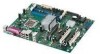
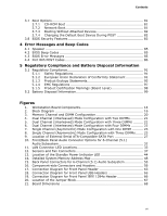
Contents 3.7 Boot Options 81 3.7.1 CD-ROM Boot 81 3.7.2 Network Boot 81 3.7.3 Booting Without Attached Devices 82 3.7.4 Changing the Default Boot Device During POST 82 3.8 BIOS Security Features 83 4 Error Messages and Beep Codes 4.1 Speaker 85 4.2 BIOS Beep Codes 85 4.3 BIOS Error Messages 85 4.4 Port 80h POST Codes 86 5 Regulatory Compliance and Battery Disposal Information 5.1 Regulatory Compliance 91 5.1.1 Safety Regulations 91 5.1.2 European Union Declaration of Conformity Statement 91 5.1.3 Product Ecology Statements 93 5.1.4 EMC Regulations 97 5.1.5 Product Certification Markings (Board Level 98 5.2 Battery Disposal Information 99 Figures 1. Workstation Board Components 14 2. Block Diagram 16 3. Memory Channel and DIMM Configuration 20 4. Dual Channel (Interleaved) Mode Configuration with Two DIMMs 21 5. Dual Channel (Interleaved) Mode Configuration with Three DIMMs ......... 21 6. Dual Channel (Interleaved) Mode Configuration with Four DIMMs 22 7. Single Channel (Asymmetric) Mode Configuration with One DIMM .......... 23 8. Single Channel (Asymmetric) Mode Configuration with Three DIMMs....... 23 9. Location of External Serial ATA-Compatible SATA Port 27 10. Front/Back Panel Audio Connector Options for 6-Channel (5.1) Audio Subsystem 32 11. LAN Connector LED Locations 33 12. Sensors and Fan Connectors 37 13. Location of the Standby Power Indicator LED 44 14. Detailed System Memory Address Map 48 15. Back Panel Connectors for 6-Channel (5.1) Audio Subsystem 55 16. Component-side Connectors and Headers 56 17. Connection Diagram for Front Panel Header 63 18. Connection Diagram for Front Panel USB Headers 65 19. Connection Diagram for Front Panel IEEE 1394a Header 66 20. Location of the Jumper Block 67 21. Board Dimensions 68 vii

  • 1
  • 2
  • 3
  • 4
  • 5
  • 6
  • 7
  • 8
  • 9
  • 10
  • 11
  • 12
  • 13
  • 14
  • 15
  • 16
  • 17
  • 18
  • 19
  • 20
  • 21
  • 22
  • 23
  • 24
  • 25
  • 26
  • 27
  • 28
  • 29
  • 30
  • 31
  • 32
  • 33
  • 34
  • 35
  • 36
  • 37
  • 38
  • 39
  • 40
  • 41
  • 42
  • 43
  • 44
  • 45
  • 46
  • 47
  • 48
  • 49
  • 50
  • 51
  • 52
  • 53
  • 54
  • 55
  • 56
  • 57
  • 58
  • 59
  • 60
  • 61
  • 62
  • 63
  • 64
  • 65
  • 66
  • 67
  • 68
  • 69
  • 70
  • 71
  • 72
  • 73
  • 74
  • 75
  • 76
  • 77
  • 78
  • 79
  • 80
  • 81
  • 82
  • 83
  • 84
  • 85
  • 86
  • 87
  • 88
  • 89
  • 90
  • 91
  • 92
  • 93
  • 94
  • 95
  • 96
  • 97
  • 98
  • 99
  • 100
  • 101
  • 102

Contents
vii
3.7
Boot Options
...................................................................................
81
3.7.1
CD-ROM Boot
......................................................................
81
3.7.2
Network Boot
.......................................................................
81
3.7.3
Booting Without Attached Devices
...........................................
82
3.7.4
Changing the Default Boot Device During POST
........................
82
3.8
BIOS Security Features
....................................................................
83
4
Error Messages and Beep Codes
4.1
Speaker
.........................................................................................
85
4.2
BIOS Beep Codes
............................................................................
85
4.3
BIOS Error Messages
.......................................................................
85
4.4
Port 80h POST Codes
.......................................................................
86
5
Regulatory Compliance and Battery Disposal Information
5.1
Regulatory Compliance
.....................................................................
91
5.1.1
Safety Regulations
................................................................
91
5.1.2
European Union Declaration of Conformity Statement
................
91
5.1.3
Product Ecology Statements
...................................................
93
5.1.4
EMC Regulations
..................................................................
97
5.1.5
Product Certification Markings (Board Level)
.............................
98
5.2
Battery Disposal Information
.............................................................
99
Figures
1.
Workstation Board Components
.........................................................
14
2.
Block Diagram
................................................................................
16
3.
Memory Channel and DIMM Configuration
...........................................
20
4.
Dual Channel (Interleaved) Mode Configuration with Two DIMMs
............
21
5.
Dual Channel (Interleaved) Mode Configuration with Three DIMMs
.........
21
6.
Dual Channel (Interleaved) Mode Configuration with Four DIMMs
...........
22
7.
Single Channel (Asymmetric) Mode Configuration with One DIMM
..........
23
8.
Single Channel (Asymmetric) Mode Configuration with Three DIMMs
.......
23
9.
Location of External Serial ATA-Compatible SATA Port
..........................
27
10. Front/Back Panel Audio Connector Options for 6-Channel (5.1)
Audio Subsystem
.............................................................................
32
11. LAN Connector LED Locations
............................................................
33
12. Sensors and Fan Connectors
.............................................................
37
13. Location of the Standby Power Indicator LED
.......................................
44
14. Detailed System Memory Address Map
...............................................
48
15. Back Panel Connectors for 6-Channel (5.1) Audio Subsystem
.................
55
16. Component-side Connectors and Headers
...........................................
56
17. Connection Diagram for Front Panel Header
........................................
63
18. Connection Diagram for Front Panel USB Headers
................................
65
19. Connection Diagram for Front Panel IEEE 1394a Header
........................
66
20. Location of the Jumper Block
.............................................................
67
21. Board Dimensions
...........................................................................
68