Intel S975XBX2 Product Specification - Page 72
Thermal Considerations
 |
UPC - 735858186506
View all Intel S975XBX2 manuals
Add to My Manuals
Save this manual to your list of manuals |
Page 72 highlights
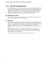
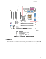
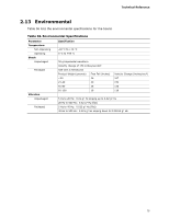
Intel Workstation Board S975XBX2 Technical Product Specification 2.11 Thermal Considerations This board features a thermal protection circuit in the processor voltage regulator area. This circuit protects the processor voltage regulator from overheating and damaging the board. The thermal protection circuit in the processor voltage regulator sensor is triggered at approximately 120 oC. This trigger will cause the processor to enter a throttling mode (slowing down the processor if it exceeds its maximum operating temperature) and allow the processor voltage regulator to cool down. # INTEGRATOR'S NOTE Use a processor heatsink that provides omni-directional airflow to maintain required airflow across the processor voltage regulator area. CAUTION When using BIOS Setup program options to increase processor voltage and frequency above the supported ranges, the temperature in the processor voltage regulator area will rise. This area of the board will require increased airflow. Direct airflow over the processor voltage regulator is crucial to preventing throttling and keeping the processor voltage regulator area cool. This is particularly important when using liquid cooling. All responsibility for determining the adequacy of any thermal or system design remains solely with the reader. Intel makes no warranties or representations that merely following the instructions presented in this document will result in a system with adequate thermal performance. Figure 23 shows the locations of the localized high temperature zones. 72
-
 1
1 -
2
-
3
-
4
-
5
-
6
-
7
-
8
-
9
-
10
-
11
-
12
-
13
-
14
-
15
-
16
-
17
-
18
-
19
-
20
-
21
-
22
-
23
-
24
-
25
-
26
-
27
-
28
-
29
-
30
-
31
-
32
-
33
-
34
-
35
-
36
-
37
-
38
-
39
-
40
-
41
-
42
-
43
-
44
-
45
-
46
-
47
-
48
-
49
-
50
-
51
-
52
-
53
-
54
-
55
-
56
-
57
-
58
-
59
-
60
-
61
-
62
-
63
-
64
-
65
-
66
-
 67
67 -
 68
68 -
 69
69 -
 70
70 -
 71
71 -
 72
72 -
 73
73 -
 74
74 -
 75
75 -
 76
76 -
 77
77 -
78
-
79
-
80
-
81
-
82
-
83
-
84
-
85
-
86
-
87
-
88
-
89
-
90
-
91
-
92
-
93
-
94
-
95
-
96
-
97
-
98
-
99
-
100
-
101
-
102
 |
 |
