Intel S975XBX2 Product Specification - Page 70
Electrical Considerations
 |
UPC - 735858186506
View all Intel S975XBX2 manuals
Add to My Manuals
Save this manual to your list of manuals |
Page 70 highlights
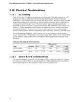
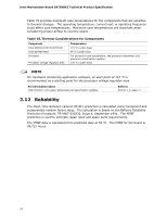
Intel Workstation Board S975XBX2 Technical Product Specification 2.10 Electrical Considerations 2.10.1 DC Loading Table 33 lists the DC loading characteristics of the board. This data is based on a DC analysis of all active components within the board that impact its power delivery subsystems. The analysis does not include PCI add-in cards. Minimum values assume a light load placed on the board that is similar to an environment with no applications running and no USB current draw. Maximum values assume a load placed on the board that is similar to a heavy gaming environment with a 500 mA current draw per USB port. These calculations are not based on specific processor values or memory configurations but are based on the minimum and maximum current draw possible from the board's power delivery subsystems to the processor, memory, and USB ports. Use the datasheets for add-in cards, such as PCI, to determine the overall system power requirements. The selection of a power supply at the system level is dependent on the system's usage model and not necessarily tied to a particular processor clock frequency. Table 33. DC Loading Characteristics Mode Minimum loading Maximum loading DC Power +3.3 V 300 W 5 A 750 W 25 A +5 V 11 A 27 A DC Current at: +12 V 19 A -12 V 0 A 46 A 0.40 A +5 VSB 0.34 A (S0) 1.25 A (S3) 0.34 A (S0) 1.25 A (S3) 2.10.2 Add-in Board Considerations The board is designed to provide 2 A (average) of +5 V current for each add-in board. The total +5 V current draw for add-in boards for the Workstation board is as follows: a fully loaded board (all five expansion slots) must not exceed 10 A. 70
-
 1
1 -
2
-
3
-
4
-
5
-
6
-
7
-
8
-
9
-
10
-
11
-
12
-
13
-
14
-
15
-
16
-
17
-
18
-
19
-
20
-
21
-
22
-
23
-
24
-
25
-
26
-
27
-
28
-
29
-
30
-
31
-
32
-
33
-
34
-
35
-
36
-
37
-
38
-
39
-
40
-
41
-
42
-
43
-
44
-
45
-
46
-
47
-
48
-
49
-
50
-
51
-
52
-
53
-
54
-
55
-
56
-
57
-
58
-
59
-
60
-
61
-
62
-
63
-
64
-
 65
65 -
 66
66 -
 67
67 -
 68
68 -
 69
69 -
 70
70 -
 71
71 -
 72
72 -
 73
73 -
 74
74 -
 75
75 -
76
-
77
-
78
-
79
-
80
-
81
-
82
-
83
-
84
-
85
-
86
-
87
-
88
-
89
-
90
-
91
-
92
-
93
-
94
-
95
-
96
-
97
-
98
-
99
-
100
-
101
-
102
 |
 |
