Intel S975XBX2 Product Specification - Page 8
Tables - memory
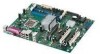 |
UPC - 735858186506
View all Intel S975XBX2 manuals
Add to My Manuals
Save this manual to your list of manuals |
Page 8 highlights
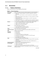
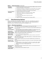
Intel Workstation Board S975XBX2 Technical Product Specification 22. I/O Shield Dimensions for Boards with the 6-Channel (5.1) Audio Subsystem 69 23. Localized High Temperature Zones 73 Tables 1. Feature Summary 12 2. Manufacturing Options 13 3. Components Shown in Figure 1 15 4. Supported Memory Configurations 18 5. Memory Operating Frequencies 19 6. LAN Connector LED States 33 7. Effects of Pressing the Power Switch 39 8. Power States and Targeted System Power 40 9. Wake-up Devices and Events 41 10. System Memory Map 49 11. DMA Channels 49 12. I/O Map 50 13. PCI Configuration Space Map 51 14. Interrupts 52 15. PCI Interrupt Routing Map 53 16. Component-side Connectors and Headers Shown in Figure 20 57 17. ATAPI CD-ROM Connector (Optional 58 18. Front Panel Audio Header 58 19. Front Chassis, Rear Chassis, and MCH Fan Headers 58 20. Processor Fan and Auxiliary Rear Fan Header 58 21. Chassis Intrusion Header 59 22. SCSI Hard Drive Activity LED Header (Optional 59 23. Serial ATA Connectors 59 24. Main Power Connector 61 25. Processor Core Power Connector (2 x 4 Pin 61 26. Processor Core Power Connector (2 x 2 Pin 61 27. Auxiliary PCI Express Graphics Power 61 28. Auxiliary Front Panel Power/Sleep LED Header 62 29. Front Panel Header 63 30. States for a One-Color Power LED 64 31. States for a Two-Color Power LED 64 32. BIOS Setup Configuration Jumper Settings 67 33. DC Loading Characteristics 70 34. Fan Header Current Capability 71 35. Thermal Considerations for Components 74 36. Environmental Specifications 75 37. BIOS Setup Program Menu Bar 78 38. BIOS Setup Program Function Keys 78 39. Boot Device Menu Options 82 40. Supervisor and User Password Functions 83 41. Beep Codes 85 viii
-
 1
1 -
2
-
 3
3 -
 4
4 -
 5
5 -
 6
6 -
 7
7 -
 8
8 -
 9
9 -
 10
10 -
 11
11 -
 12
12 -
 13
13 -
14
-
15
-
16
-
17
-
18
-
19
-
20
-
21
-
22
-
23
-
24
-
25
-
26
-
27
-
28
-
29
-
30
-
31
-
32
-
33
-
34
-
35
-
36
-
37
-
38
-
39
-
40
-
41
-
42
-
43
-
44
-
45
-
46
-
47
-
48
-
49
-
50
-
51
-
52
-
53
-
54
-
55
-
56
-
57
-
58
-
59
-
60
-
61
-
62
-
63
-
64
-
65
-
66
-
67
-
68
-
69
-
70
-
71
-
72
-
73
-
74
-
75
-
76
-
77
-
78
-
79
-
80
-
81
-
82
-
83
-
84
-
85
-
86
-
87
-
88
-
89
-
90
-
91
-
92
-
93
-
94
-
95
-
96
-
97
-
98
-
99
-
100
-
101
-
102
 |
 |