Intel SE7520BD2 User Guide
Intel SE7520BD2 Manual
 |
View all Intel SE7520BD2 manuals
Add to My Manuals
Save this manual to your list of manuals |
Intel SE7520BD2 manual content summary:
- Intel SE7520BD2 | User Guide - Page 1
Intel® Server Board SE7520BD2 User Guide A Guide for Technically Qualified Assemblers of Intel® Identified Subassemblies/Products Order Number: C51518-007 - Intel SE7520BD2 | User Guide - Page 2
product could create a situation where personal injury or death may occur. Intel may make changes to specifications and product descriptions at any time, without notice. Intel server boards contain a number of high-density VLSI and power delivery components that need adequate airflow for cooling - Intel SE7520BD2 | User Guide - Page 3
Product Specification. Chapter 4 provides troubleshooting information. In this chapter, you will find BIOS error messages and POST code messages. You will also find suggestions for performing troubleshooting activities to identify the source of a problem. Intel® Server Board SE7520BD2 User Guide - Intel SE7520BD2 | User Guide - Page 4
this document / software Intel® Server Board SE7520BD2 Technical Product Specification Intel® Server Board SE7520BD2 Quick Start User's Guide located in the product box or to obtain a newer version, use this link: Quick Start User's Guide. Spares and Configuration Guide Document Tested Hardware and - Intel SE7520BD2 | User Guide - Page 5
sure your system falls within the allowed power budget For software to manage your Intel® Server For firmware, BIOS updates, and drivers Supported Processor List Tested Memory List Power Budget Tool Intel® Server Management Software Download Finder To obtain the documents or software mentioned - Intel SE7520BD2 | User Guide - Page 6
and safety statements in this document before performing any of the instructions. See also Intel Server Boards and Server Chassis Safety Information on the Deployment CD and/or at http://support.intel.com/support/motherboards/server/sb/CS-010770.htm Wichtige Sicherheitshinweise Lesen Sie zunächst - Intel SE7520BD2 | User Guide - Page 7
y precaución de este documento antes de realizar cualquiera de las instrucciones. Vea Intel Server Boards and Server Chassis Safety Information en el CD Resource y/o en http://support.intel.com/support/motherboards/server/sb/CS-010770.htm AVVERTENZA: Italiano PASSI DI SICUREZZA: Qualora si rimuovano - Intel SE7520BD2 | User Guide - Page 8
Preface viii - Intel SE7520BD2 | User Guide - Page 9
Board Features 13 Connector and Header Locations 18 Product Codes SE7520BD2, SE7520BD2SCSI, SE7520BD2V 18 Product Codes SE7520BD2SCSID2, SE7520BD2VD2, SE7520BD2SATAD2 20 Configuration Jumpers ...22 Back Panel Connectors...23 Hardware Requirements ...24 Server Chassis ...24 Processor ...24 Memory - Intel SE7520BD2 | User Guide - Page 10
50 System Cooling Fans Do Not Rotate Properly 50 Diskette Drive Activity Light Does Not Light 50 CD-ROM Drive or DVD-ROM Drive Activity Light Does Not Light 51 Cannot Connect to a Server 51 Problems with Network 51 System Boots when Installing PCI Card 52 Problems with Newly Installed - Intel SE7520BD2 | User Guide - Page 11
Figure 1. Intel® Server Board SE7520BD2 13 Figure 2. Product Codes SE7520BD2, SE7520BD2SCSI, and SE7520BD2V Connector and Header Locations...19 Figure 3. Product Codes SE7520BD2SCSID2, SE7520BD2VD2, and SE7520BD2SATAD2 Connector and Header Locations 21 Figure 4. Configuration Jumper Location - Intel SE7520BD2 | User Guide - Page 12
Contents xii - Intel SE7520BD2 | User Guide - Page 13
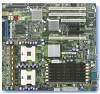
important components and connections on the server board. Figure 1. Intel® Server Board SE7520BD2 Six product codes for the Server Board SE7520BD2 are available. The following table provides an overview of the differences between them, by product code. Intel® Server Board SE7520BD2 User Guide 13 - Intel SE7520BD2 | User Guide - Page 14
Server Board Features Table 1. Server Board Varieties Product Code Memory PCI SCSI Product code SE7520BD2 Product code SE7520BD2SATAD2 Six DIMM sockets DDR 266/333 72-bit, 184-pin DIMMs Supported DIMM sizes: 256 MB, 512 MB, 1 GB, 2 GB, 4 GB 24 GB Maximum (when 4 GB DIMMs are available) Dual - Intel SE7520BD2 | User Guide - Page 15
Server Board Features Table 1. Server Board Varieties (continued) Product Code Memory PCI SCSI SATA USB Connections Product code SE7520BD2SCSI Product code SE7520BD2SCSID2 Six DIMM sockets DDR 266/333 72-bit, 184-pin DIMMs Supported DIMM sizes: 256MB, 512MB, 1GB, 2GB, 4GB 24 GB Maximum ( - Intel SE7520BD2 | User Guide - Page 16
Server Board Features Table 1. Server Board Varieties (continued) Product Code Memory PCI SCSI SATA USB Connections Product code SE7520BD2V Product code SE7520BD2VD2 Six DIMM sockets DDR 266/333 72-bit, 184-pin DIMMs Supported DIMM sizes: 256MB, 512MB, 1GB, 2GB, 4GB 24 GB Maximum (when 4 GB - Intel SE7520BD2 | User Guide - Page 17
FC-mPGA4 using Socket 604, and an 800-MHz Front Side Bus (FSB) Memory Chipset See Table 1 Intel® E7520 chipset: ƒ Supports 800 MHz Front Side Bus (FSB) ƒ Intel® E7520 Memory Controller Hub (MCH) ƒ Intel® 6700PXH 64-bit PCI Hub ƒ Intel® 82801ER I/O Controller Hub5 (ICH-5R) I/O Control Video Hard - Intel SE7520BD2 | User Guide - Page 18
Server Board Features Connector and Header Locations Product Codes SE7520BD2, SE7520BD2SCSI, SE7520BD2V G A BCDE F H I L J KM TT SS RR QQ PP NN OO MM LL KK JJ II HH GG FF CPU 2 DD BB Z X W EE AA VU T CC Y N O P Q R CPU 1 S TP00718 18 - Intel SE7520BD2 | User Guide - Page 19
Left x8 (x4speed) PCI-Express* Slot F, Right x8 PCI-Express Slot G Intel® 82541P1 (10/100/1000) H PCI-X 133 Slot I Battery P CPU Power Connector Q DIMM Sockets R CPU 1 Fan Header S CPU 1 T CPU 2 U Intel® Management Module Connector V IDE Connector W Floppy Connector X System Fan 2 (3-pin) Y System - Intel SE7520BD2 | User Guide - Page 20
Server Board Features Product Codes SE7520BD2SCSID2, SE7520BD2VD2, SE7520BD2SATAD2 G A BCDE F H I L J KM TT SS RR QQ PP NN OO MM LL KK JJ II HH GG FF CPU 2 DD BB Z X W EE AA VU T CC Y CPU 1 N O P O Q R S TP01688 20 - Intel SE7520BD2 | User Guide - Page 21
Power Connector O Main Power Connector P CPU Power Connector Q DIMM Sockets R CPU 1 Fan Header S CPU 1 T CPU 2 U Intel® Management Module Connector V IDE Connector W Floppy Connector X System Fan 2 (3-pin) Y System Fan 2 (2-pin) Z System Fan 1 (2-pin) AA HSBP A BB Front Panel USB CC Front Panel - Intel SE7520BD2 | User Guide - Page 22
Server Board Features Configuration Jumpers BIOS SEL Normal 3 J1B1 Bank 0 CMOS CLR RECOVERY BOOT J4H1 FRB HALT 3 J2H1 3 J4H3 J4H2 PASSWORD CLEAR TP00723 Figure 4. Configuration Jumper Location Table 3. Configuration Jumpers Jumper Name Pins What happens at system reset... CMOS Clear - Intel SE7520BD2 | User Guide - Page 23
G Video H NIC1 (Management port) I NIC2 Note: USB3 is available only on product codes SE7520BD2 and SE7520BD2SCSI Figure 5. Back Panel Connectors The NIC LEDs at the right and left of the NICs provide the following information. See the Intel® Server Board SE7520BD2 Technical Product Specification - Intel SE7520BD2 | User Guide - Page 24
SE7520BD2SCSID2 Supported Supported Supported Supported Supported Supported SE7520BD2VD2 Supported Supported Supported Supported Supported Supported Processor The Intel® Server Board SE7520BD2 (all product codes) supports up to two Intel® Xeon™ processors with an FC-mPGA4 using Socket 604 - Intel SE7520BD2 | User Guide - Page 25
-333 memory is only supported with BGA package memory on the Intel® Server Board SE7520BD2 (product codes SE7520BD2, SE7520BD2SCSO, SE7520BD2V). TSOP SDRAM packages will not be supported on DDR-333 DIMMs on these product codes. ƒ A minimum of one 256MB DIMM is required in DIMM socket 1B. This uses - Intel SE7520BD2 | User Guide - Page 26
edge of the server board. DIMMs must be identical within each bank. The minimum allowed memory is 256 MB, using a single 256 MB DIMM in DIMM slot 1B. The system operates in single channel when only a single DIMM is installed. The maximum allowed usable memory is 16 GB of DDR2-400, using 2 GB DIMMs - Intel SE7520BD2 | User Guide - Page 27
its place. When memory on-line sparing is used, the spare DIMMs must be equal to or larger than the largest in-service DIMM in that channel. For additional information, see the Intel® Server Board SE7520BD2 Technical Product Specification. Power Supply The minimum power supply required depends on - Intel SE7520BD2 | User Guide - Page 28
server product, pay close attention to the "Safety Information" at the beginning of this manual. ✏ NOTES Most diagrams in this manual show product code SE7520BD2. Where necessary to complete a procedure, differences are noted. Tools and Supplies Needed ƒ Phillips* (cross head) screwdriver (#1 bit - Intel SE7520BD2 | User Guide - Page 29
AC power cord from the server. 4. Remove the chassis cover. See your chassis documentation for instructions. 5. Locate the DIMM sockets. See Figure 6. ✏ NOTES The diagram below shows product code SE7520BD2. If you are using a Server Board SE7520BD2 that supports DDR2 memory DIMMs, your server board - Intel SE7520BD2 | User Guide - Page 30
the DIMM sockets. 8. Replace the chassis cover and reconnect the AC power cord. Installing or Replacing the Processor CAUTIONS Processor must be appropriate: You may damage the server board if you install a processor that is inappropriate for your server. See Supported Processor List for compatible - Intel SE7520BD2 | User Guide - Page 31
this book. 2. Turn off all peripheral devices connected to the server. Turn off the server. 3. Disconnect the AC power cord from the server. 4. Remove the chassis cover and locate the processor sockets. 5. Locate the processor socket and raise the socket handle completely. TP00725 Figure 7. Opening - Intel SE7520BD2 | User Guide - Page 32
Lower the socket lever completely. TP00865 Figure 9. Closing Socket Lever Installing the Heat Sink(s) 1. The heat sink has Thermal Interface Material (TIM) located on the bottom of it. Use caution when . See the boxed processor documentation for specifc instructions for the thermal solution. 32 - Intel SE7520BD2 | User Guide - Page 33
Hardware Installations and Upgrades Note: Heat sink styles may differ. Server Board Cutaway Heat Sink Retainer [CEK Spring] TP00721 Figure 10. Installing the Heat Sink 33 - Intel SE7520BD2 | User Guide - Page 34
full-height riser card slot, it must be equipped with a standard full-height PCI mounting bracket. WARNING Do not attempt to remove a PCI card without turning off the system first. 1. Remove the chassis cover. 2. See the chassis Quick Start User's Guide for instructions on removing any chassis - Intel SE7520BD2 | User Guide - Page 35
battery on the server board powers the RTC for up to 10 years in the absence of power. When the battery starts to weaken, it loses voltage, and the server settings stored in CMOS RAM in the RTC (for example, the date and time) may be wrong. Contact your customer service representative or dealer - Intel SE7520BD2 | User Guide - Page 36
lithium battery from its package, and observe the correct polarity. The flat side of the battery that has a "+" on it must face toward the DIMM slots. 9 Insert the battery in the socket. 10 Close the chassis. 11 Run Setup to restore the configuration settings to the RTC. 36 - Intel SE7520BD2 | User Guide - Page 37
Setup Utility options, which is used to change server configuration defaults. You can run BIOS Setup with or without an operating system present. See the Intel® Server Board SE7520BD2 Technical Product Specification for additional details about specific BIOS setup screens. Starting Setup You can - Intel SE7520BD2 | User Guide - Page 38
Server Utilities Table 6 describes the keyboard commands you can use in the BIOS Setup menus. Table 6. Keyboard Commands Press Description Help - Pressing F1 on any menu invokes the general Help window. The left and right arrow keys are used the user is Save Configuration changes - Intel SE7520BD2 | User Guide - Page 39
will need these settings to configure your computer at the end of the procedure. Obtaining the Upgrade Download the latest BIOS image file to a temporary folder on your hard drive. See Download Finder for a link to the BIOS update software. ✏ NOTE Review the instructions distributed with the upgrade - Intel SE7520BD2 | User Guide - Page 40
Power cycle the system. 7. Press to enter BIOS Setup, and re-enter the custom values recorded earlier. Press to save the values and exit Setup. 8. In the unlikely event that a BIOS error occurs during the BIOS update process, see "Recovering the BIOS" for instructions on performing a BIOS - Intel SE7520BD2 | User Guide - Page 41
the BIOS" for instructions on performing a BIOS recovery. You can obtain the Recovery.zip file which is packaged together with the BIOS Update Package from the Intel Support Web site at Download Finder. There are two options in creating a recovery disk: ƒ Creating a Recovery Disk Using Floppy - Intel SE7520BD2 | User Guide - Page 42
to return the system to service. Two methods are available to recover the BIOS: automatically with the crisis recovery diskette, and manually by moving a jumper on the system board. These methods are described below. ✏ NOTE BIOS recovery is the mode of last resort, used only when the main system - Intel SE7520BD2 | User Guide - Page 43
Server Utilities Manually Recovering the BIOS A BIOS recovery can be manually initiated. This option would be used only when the BIOS is corrupt, but the ROM checksum error does not occur during POST. To manually initiate a BIOS recovery, use the following steps: 1. Power down and uplug the system - Intel SE7520BD2 | User Guide - Page 44
jumper must be removed before a new password(s) can be set. 1. Power down the system and disconnect the AC power. 2. Open the server chassis. 3. Install the jumper on jumper block J4H3, as shown in the following diagram. RECOVERY BOOT J4H1 FRB HALT 3 J4H3 J4H2 PASSWORD CLEAR TP00902 Figure 13 - Intel SE7520BD2 | User Guide - Page 45
If you are not able to access the BIOS setup screens, the Clear CMOS jumper will need to be used to reset the configuration RAM. The Clear CMOS jumper is located on jumper block J2H1. 1. Power down the system and disconnect the AC power. 2. Open the server. 3. Move the jumper from pins 1 and 2 to - Intel SE7520BD2 | User Guide - Page 46
. In addition to the server firmware and files, also update any drivers used for components you have installed in your system, such as video drivers, network drivers, and SCSI drivers. Intel provides a package called the "Platform Confidence Test" that may help with your diagnostics. See "Additional - Intel SE7520BD2 | User Guide - Page 47
the configuration settings made in Setup correct? ‰ Is the operating system properly loaded? See the operating system documentation. ‰ Did you press the system power on/off switch on the front panel to turn the server on (power on light should be lit)? ‰ Is the system power cord properly connected - Intel SE7520BD2 | User Guide - Page 48
the problem, contact your service representative or authorized dealer for help. Power Light Does Not Light Check the following: ‰ Did you press the power-on button? ‰ Is the system operating normally? If so, the power LED might be defective or the cable from the front panel to the server board might - Intel SE7520BD2 | User Guide - Page 49
seated in the server board connector. 3. Reboot the system for changes to take effect. 4. If there are still no characters on the screen after you reboot the system and POST emits a beep code, write down the beep code you hear. This information is useful for your service representative. 5. If you - Intel SE7520BD2 | User Guide - Page 50
fans speeded up in response to a fan that has failed? ‰ Are the fan power connectors properly connected to the server board? ‰ Is the cable from the front panel board connected to both the front panel board and the server board? ‰ Are the power supply cables properly connected to the server board - Intel SE7520BD2 | User Guide - Page 51
need a crossover cable. ‰ Check the network controller LEDs next to the NIC connectors. Problems with Network The server hangs when the drivers are loaded. ‰ Certain drivers may require interrupts that are not shared with other PCI drivers. For these drivers, it may be necessary to alter settings so - Intel SE7520BD2 | User Guide - Page 52
panel. If you install a PCI card with the AC power cord plugged in, a signal may be sent to reboot the system. Before installing a PCI card, you should always: ‰ Turn off the server power by using the power button on the front of the system. ‰ Unplug the AC power cord(s) from the server. Problems - Intel SE7520BD2 | User Guide - Page 53
the RAID card is installed correctly and properly configured. Bootable CD-ROM Is Not Detected Check the following: ‰ Make sure the BIOS is configured to allow the CD-ROM to be the first bootable device. LED Information The Intel® Server Board SE7520BD2 includes LEDs that can aid in troubleshooting - Intel SE7520BD2 | User Guide - Page 54
video initialization, the BIOS uses these beep codes to inform users of error conditions. Table 8. POST Error Beep Codes Number of Description Beeps 1 Memory refresh timer error 2 Parity error in base memory (first 64KB block) 3 Base memory read / write test error 4 Motherboard timer - Intel SE7520BD2 | User Guide - Page 55
BIOS Beep Codes Table 9. BIOS Beep Codes Number of Troubleshooting Action Beeps 1, 2 or 3 Reseat the memory, or replace with known good modules. 4-7, 9-11 Fatal error indicating a serious problem with the system. Consult your system manufacturer. Before declaring the motherboard - Intel SE7520BD2 | User Guide - Page 56
type market place. Intel targets 10db margin to Class A Limits The Intel® Server Board SE7520BD2 has been tested and verified to comply with the following electromagnetic compatibility (EMC) regulations when installed in a compatible Intel (EMI) (Korea) Intel® Server Board SE7520BD2 User Guide 56 - Intel SE7520BD2 | User Guide - Page 57
Regulatory and Compliance Information Certifications/Registrations/Declarations ƒ UL Certification (US/Canada) ƒ CE Declaration of Conformity (CENELEC Europe) ƒ FCC/ICES-003 Class A Attestation (USA/Canada) ƒ C-Tick Declaration of Conformity (Australia) ƒ MED Declaration of Conformity (New Zealand) - Intel SE7520BD2 | User Guide - Page 58
Compatibility , contact: Intel Corporation 5200 uses, and can radiate radio frequency energy and, if not installed and used in accordance with the instructions off and on, the user is encouraged to try used to connect to peripherals must be shielded and grounded. Operation with cables, connected - Intel SE7520BD2 | User Guide - Page 59
the above notice: 1. Type of Equipment (Model Name): On License and Product 2. Certification No.: On RRL certificate. Obtain certificate from local Intel representative 3. Name of Certification Recipient: Intel Corporation 4. Date of Manufacturer: Refer to date code on product 5. Manufacturer/Nation - Intel SE7520BD2 | User Guide - Page 60
Wide Web http://support.intel.com/support/motherboards/server/SE7520BD2 Telephone All calls are billed US $25.00 per incident, levied in local currency at the applicable credit card exchange rate plus applicable taxes. (Intel reserves the right to change the pricing for telephone support at any - Intel SE7520BD2 | User Guide - Page 61
at 0 800 2255 288. Once connected, dial 800 843 4481 Argentina Contact AT&T USA at 0-800 222 1288. Once connected, dial 800 843 4481 Paraguay 001 916 377 0114 Peru 001 916 377 0114 Uruguay 001 916 377 0114 For an updated support contact list, see http://www.intel.com/support/9089.htm/ 61 - Intel SE7520BD2 | User Guide - Page 62
detailed problem description. Board / Chassis Information Baseboard Revision - PBA#: DIMM Configuration Baseboard Serial Number: DIMM1B MB, Vendor/part number CPU1 Speed/Stepping/Spec: DIMM1A MB, Vendor/part number CPU2 Speed/Stepping/Spec: DIMM2B MB, Vendor/part number System BIOS Version - Intel SE7520BD2 | User Guide - Page 63
Intel® Server Issue Report Form Operating System Information Operating System Version Service Pack / Kernel Version General Information. Check each box below that is used, and provide the requested information. Peripheral Video ˆ ˆ NIC ˆ ˆ PCI-X* 100 Slot 1 PCI-X 100 Slot 2 PCI 32/33 - Intel SE7520BD2 | User Guide - Page 64
Intel® Server Issue Report Form Complete Issue Description In the space below, provide a complete description of the steps used to reproduce the issue or a complete description of where the problem can be found. Please also include any details on troubleshooting already done. 64
-
 1
1 -
 2
2 -
 3
3 -
 4
4 -
 5
5 -
 6
6 -
 7
7 -
8
-
9
-
10
-
11
-
12
-
13
-
14
-
15
-
16
-
17
-
18
-
19
-
20
-
21
-
22
-
23
-
24
-
25
-
26
-
27
-
28
-
29
-
30
-
31
-
32
-
33
-
34
-
35
-
36
-
37
-
38
-
39
-
40
-
41
-
42
-
43
-
44
-
45
-
46
-
47
-
48
-
49
-
50
-
51
-
52
-
53
-
54
-
55
-
56
-
57
-
58
-
59
-
60
-
61
-
62
-
63
-
64
 |
 |

Intel® Server Board SE7520BD2
User Guide
A Guide for Technically Qualified Assemblers of Intel
®
Identified
Subassemblies/Products
Order Number:
C51518-00
7