Intel SE7520BD2 User Guide - Page 19
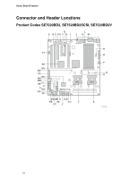
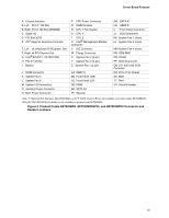
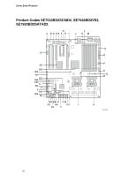
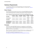
Product Codes SE7520BD2, SE7520BD2SCSI, and SE7520BD2V Connector and, Header Locations
 |
View all Intel SE7520BD2 manuals
Add to My Manuals
Save this manual to your list of manuals |
Page 19 highlights
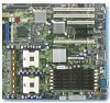
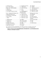
Server Board Features A Chassis Intrusion B, Left PCI-X* 100 Slot B, Right PCI-X 100 Slot (MROMB) C Super I/O D PCI Slot 32/33 E ATI* Rage XL Graphics Controller F, Left x8 (x4speed) PCI-Express* Slot F, Right x8 PCI-Express Slot G Intel® 82541P1 (10/100/1000) H PCI-X 133 Slot I Battery P CPU Power Connector Q DIMM Sockets R CPU 1 Fan Header S CPU 1 T CPU 2 U Intel® Management Module Connector V IDE Connector W Floppy Connector X System Fan 2 (3-pin) Y System Fan 2 (2-pin) Z System Fan 1 (2-pin) J ICMB Connector K System Fan 5 L System Fan 6 M System I/O Connectors N Auxiliary Power Connector O Main Power Connector AA HSBP A BB Front Panel USB CC Front Panel LCP DD IPMB EE SATA A2 FF Speaker GG SATA A1 HH HSBP B II Front Panel Connector JJ SCSI Channel A KK System Fan 1 (3-pin) LL System Fan 3 (6-pin) MM System Fan 4 (6-pin) NN OEM RMC OO ICH5R PP SCSI Channel B QQ LSI* 53C1030 SCSI Controller RR CPU 2 Fan Header SS MCH TT PHX UU Serial B Header Note: F, Right (x8 PCI Express), NN (OEM RMC), and PP (SCSI Channel B) are not available on product codes SE7520BD2V. QQ (LSI* 53C1030 SCSI Controller) is not available on product code SE7520BD2. Figure 2. Product Codes SE7520BD2, SE7520BD2SCSI, and SE7520BD2V Connector and Header Locations 19
-
 1
1 -
2
-
3
-
4
-
5
-
6
-
7
-
8
-
9
-
10
-
11
-
12
-
13
-
 14
14 -
 15
15 -
 16
16 -
 17
17 -
 18
18 -
 19
19 -
 20
20 -
 21
21 -
 22
22 -
 23
23 -
 24
24 -
25
-
26
-
27
-
28
-
29
-
30
-
31
-
32
-
33
-
34
-
35
-
36
-
37
-
38
-
39
-
40
-
41
-
42
-
43
-
44
-
45
-
46
-
47
-
48
-
49
-
50
-
51
-
52
-
53
-
54
-
55
-
56
-
57
-
58
-
59
-
60
-
61
-
62
-
63
-
64
 |
 |