Intel SE7520BD2 User Guide - Page 11

s, Tables - socket

Page 11 highlights

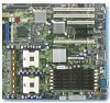
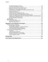
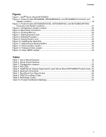
Contents Figures Figure 1. Intel® Server Board SE7520BD2 13 Figure 2. Product Codes SE7520BD2, SE7520BD2SCSI, and SE7520BD2V Connector and Header Locations...19 Figure 3. Product Codes SE7520BD2SCSID2, SE7520BD2VD2, and SE7520BD2SATAD2 Connector and Header Locations 21 Figure 4. Configuration Jumper Location 22 Figure 5. Back Panel Connectors 23 Figure 6. Installing Memory...29 Figure 7. Opening Socket Lever 31 Figure 8. Inserting Processor...31 Figure 9. Closing Socket Lever 32 Figure 10. Installing the Heat Sink 33 Figure 11. Replacing the Backup Battery 36 Figure 12. Recovery Boot Jumper 43 Figure 13. Password Clear Jumper 44 Figure 14. Clear CMOS Jumper 45 Tables Table 1. Server Board Varieties 14 Table 2. Server Board Features 17 Table 3. Configuration Jumpers 22 Table 4. NIC LEDs ...23 Table 5. Intel® Server Chassis Supported for each Server Board SE7520BD2 Product Code.. 24 Table 6. Keyboard Commands 38 Table 7. Boot Block Error Beep Codes 54 Table 8. POST Error Beep Codes 54 Table 9. BIOS Beep Codes...55 Table 10. Product Certification Markings 57 xi

  • 1
  • 2
  • 3
  • 4
  • 5
  • 6
  • 7
  • 8
  • 9
  • 10
  • 11
  • 12
  • 13
  • 14
  • 15
  • 16
  • 17
  • 18
  • 19
  • 20
  • 21
  • 22
  • 23
  • 24
  • 25
  • 26
  • 27
  • 28
  • 29
  • 30
  • 31
  • 32
  • 33
  • 34
  • 35
  • 36
  • 37
  • 38
  • 39
  • 40
  • 41
  • 42
  • 43
  • 44
  • 45
  • 46
  • 47
  • 48
  • 49
  • 50
  • 51
  • 52
  • 53
  • 54
  • 55
  • 56
  • 57
  • 58
  • 59
  • 60
  • 61
  • 62
  • 63
  • 64

Contents
xi
Figures
Figure 1. Intel
®
Server Board SE7520BD2
................................................................................
13
Figure 2. Product Codes SE7520BD2, SE7520BD2SCSI, and SE7520BD2V Connector and
Header Locations
.................................................................................................................
19
Figure 3. Product Codes SE7520BD2SCSID2, SE7520BD2VD2, and SE7520BD2SATAD2
Connector and Header Locations
........................................................................................
21
Figure 4. Configuration Jumper Location
....................................................................................
22
Figure 5. Back Panel Connectors
...............................................................................................
23
Figure 6. Installing Memory
.........................................................................................................
29
Figure 7. Opening Socket Lever
.................................................................................................
31
Figure 8. Inserting Processor
......................................................................................................
31
Figure 9. Closing Socket Lever
...................................................................................................
32
Figure 10. Installing the Heat Sink
..............................................................................................
33
Figure 11. Replacing the Backup Battery
...................................................................................
36
Figure 12. Recovery Boot Jumper
..............................................................................................
43
Figure 13. Password Clear Jumper
............................................................................................
44
Figure 14. Clear CMOS Jumper
.................................................................................................
45
Tables
Table 1. Server Board Varieties
..................................................................................................
14
Table 2. Server Board Features
..................................................................................................
17
Table 3. Configuration Jumpers
..................................................................................................
22
Table 4. NIC LEDs
......................................................................................................................
23
Table 5. Intel® Server Chassis Supported for each Server Board SE7520BD2 Product Code.. 24
Table 6. Keyboard Commands
...................................................................................................
38
Table 7. Boot Block Error Beep Codes
.......................................................................................
54
Table 8. POST Error Beep Codes
..............................................................................................
54
Table 9. BIOS Beep Codes
.........................................................................................................
55
Table 10. Product Certification Markings
....................................................................................
57