Intel SR1530HCLS Product Specification - Page 31
Front Control Panel - SR1530HCL/SR1530HCLR SATA and, SR1530HCLS/SR1530HCLSR SAS
 |
View all Intel SR1530HCLS manuals
Add to My Manuals
Save this manual to your list of manuals |
Page 31 highlights
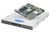
Intel® Server Systems SR1530CL/SR1530HCL/SR1530HCS and SR1530CLR/SR1530HCLR/SR1530HCLSR Front Control Panel Figure 19. Front Control Panel - SR1530HCL/SR1530HCLR (SATA) and SR1530HCLS/SR1530HCLSR (SAS) Item A B C D E F G NIC 1 LED Feature NIC 2 LED System power LED System power LED Hard drive activity LED Hard drive activity LED Power button. This button also functions as a sleep button if enabled by an ACPI-compliant operating system. Table 17. Control Panel LED Functions LED NIC1/NIC2 Activity Power/Sleep (on standby power) Color Green Green Green Off Green System Status (on standby power) Amber Disk Activity Off Green Off State On Blink On Blink Off On Blink On Blink Off Random blink Off Description NIC Link/no access LAN access Power on Sleep/ACPI S1 state Power Off/ACPI S4 state Running/normal operation System ready, but degraded Critical or non-recoverable condition. Possible critical power module failure, critical fan failure, voltage (power supply), voltage and thermal fault Non-critical condition. POST/system stop. System not ready HDD access No hard disk activity Revision 2.2 23 Intel order number D71005-005
-
 1
1 -
2
-
3
-
4
-
5
-
6
-
7
-
8
-
9
-
10
-
11
-
12
-
13
-
14
-
15
-
16
-
17
-
18
-
19
-
20
-
21
-
22
-
23
-
24
-
25
-
 26
26 -
 27
27 -
 28
28 -
 29
29 -
 30
30 -
 31
31 -
 32
32 -
 33
33 -
 34
34 -
 35
35 -
 36
36 -
37
-
38
-
39
-
40
-
41
-
42
-
43
-
44
-
45
-
46
-
47
-
48
-
49
-
50
-
51
-
52
-
53
-
54
-
55
-
56
 |
 |
