Intel SR1530HCLS Product Specification - Page 50
Appendix B: POST Code Diagnostic LED Decoder, Diagnostic LEDs
 |
View all Intel SR1530HCLS manuals
Add to My Manuals
Save this manual to your list of manuals |
Page 50 highlights
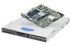
Appendix B: POST Code Diagnostic LED Decoder Intel® Server Systems SR1530CL/SR1530HCL/SR1530HCS and SR1530CLR/SR1530HCLR/SR1530HCLSR Appendix B: POST Code Diagnostic LED Decoder During the system boot process, BIOS executes a number of platform configuration processes, each of which is assigned a specific hex POST code number. As each configuration routine is started, BIOS will display the given POST code to the POST Code Diagnostic LEDs found on the back edge of the server board. To assist in troubleshooting a system hang during the POST process, the Diagnostic LEDs can be used to identify the last POST process to be executed. Each POST code will be represented by a combination of colors from the four LEDs. The LEDs are capable of displaying three colors: green, red, and amber. The POST codes are divided into two nibbles, an upper nibble and a lower nibble. Each bit in the upper nibble is represented by a red LED and each bit in the lower nibble is represented by a green LED. If both bits are set in the upper and lower nibbles then both red and green LEDs are lit, resulting in an amber color. If both bits are clear, then the LED is off. In the below example, BIOS sends a value of ACh to the diagnostic LED decoder. The LEDs are decoded as follows: ƒ red bits = 1010b = Ah ƒ green bits = 1100b = Ch Since the red bits correspond to the upper nibble and the green bits correspond to the lower nibble, the two are concatenated to be ACh. LEDs ACh Result Table 29: POST Progress Code LED Example Red 1 8h Green 1 Amber MSB Red 0 Green 4h Green 1 Red 1 Red 2h Green 0 Red 0 Off 1h Green 0 LSB USB Port USB Port Back edge of baseboard Diagnostic LEDs MSB LSB Figure 22. Diagnostic LED Placement Diagram Example 42 Revision 2.2 Intel order number D71005-005
-
 1
1 -
2
-
3
-
4
-
5
-
6
-
7
-
8
-
9
-
10
-
11
-
12
-
13
-
14
-
15
-
16
-
17
-
18
-
19
-
20
-
21
-
22
-
23
-
24
-
25
-
26
-
27
-
28
-
29
-
30
-
31
-
32
-
33
-
34
-
35
-
36
-
37
-
38
-
39
-
40
-
41
-
42
-
43
-
44
-
 45
45 -
 46
46 -
 47
47 -
 48
48 -
 49
49 -
 50
50 -
 51
51 -
 52
52 -
 53
53 -
 54
54 -
 55
55 -
56
 |
 |
