Intel SR1530HCLS Product Specification - Page 5

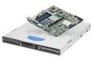
List of s, Drive Bays - SR1530HCL/SR1530HCLR SATA and SR1530HCLS/SR1530HCLSR - sr1530clr

Page 5 highlights

Intel® Server Systems SR1530CL/SR1530HCL/SR1530HCS and SR1530CLR/SR1530HCLR/SR1530HCLSR List of Figures List of Figures Figure 1. Intel® Server System SR1530CL/SR1530CLR (SATA 1 Figure 2. Intel® Server Systems SR1530HCL/SR1530HCLR (SATA) and SR1530HCLS/SR1530HCLSR (SAS 2 Figure 3. Major System Components - SR1530CL/SR1530CLR (SATA 3 Figure 4. Major System Components - SR1530HCL/SR1530HCLR (SATA) and SR1530HCLS/SR1530HCLSR (SAS 4 Figure 5. Back Panel Features ...5 Figure 6. Drive Bays (SR1530CL/SR1530CLR 6 Figure 7. Drive Bays - SR1530HCL/SR1530HCLR (SATA) and SR1530HCLS/SR1530HCLSR (SAS)...6 Figure 8. Power Supply Mechanical Drawing 8 Figure 9. AC Power Cord Specifications 13 Figure 10. Fan Module Assembly - SR1530CL/SR1530CLR (SATA 14 Figure 11. Fan Module Assembly - SR1530HCL/SR1530HCLR (SATA) and SR1530HCLS/SR1530HCLSR (SAS 15 Figure 12. Air Baffle (SR1530CL/SR1530CLR 16 Figure 13. Air Baffle (SR1530HCL/SR1530HCLR 16 Figure 14. Drive Bays SR1530CL/SR1530CLR (SATA 17 Figure 15. Drive Bays - SR1530HCL/SR1530HCLR (SATA) and SR1530HCLS/SR1530HCLSR (SAS)...18 Figure 16. Hard Drive Tray Assembly 20 Figure 17. Drive Tray with Drive Blank 20 Figure 18. Front Control Panel - SR1530CL/SR1530CLR (SATA 22 Figure 19. Front Control Panel - SR1530HCL/SR1530HCLR (SATA) and SR1530HCLS/SR1530HCLSR (SAS 23 Figure 20. PCI Riser Card Assembly 26 Figure 21. Hot Swap Passive Backplane - SR1530HCL/SR1530HCLR (SATA) and SR1530HCLS/SR1530HCLSR (SAS 27 Figure 22. Diagnostic LED Placement Diagram Example 42 Revision 2.2 v Intel order number D71005-005

  • 1
  • 2
  • 3
  • 4
  • 5
  • 6
  • 7
  • 8
  • 9
  • 10
  • 11
  • 12
  • 13
  • 14
  • 15
  • 16
  • 17
  • 18
  • 19
  • 20
  • 21
  • 22
  • 23
  • 24
  • 25
  • 26
  • 27
  • 28
  • 29
  • 30
  • 31
  • 32
  • 33
  • 34
  • 35
  • 36
  • 37
  • 38
  • 39
  • 40
  • 41
  • 42
  • 43
  • 44
  • 45
  • 46
  • 47
  • 48
  • 49
  • 50
  • 51
  • 52
  • 53
  • 54
  • 55
  • 56

Intel® Server Systems SR1530CL/SR1530HCL/SR1530HCS
List of Figures
and SR1530CLR/SR1530HCLR/SR1530HCLSR
Revision 2.2
Intel order number D71005-005
v
List of Figures
Figure 1. Intel
®
Server System SR1530CL/SR1530CLR (SATA)
.................................................
1
Figure 2. Intel
®
Server Systems SR1530HCL/SR1530HCLR (SATA) and
SR1530HCLS/SR1530HCLSR (SAS)
....................................................................................
2
Figure 3. Major System Components - SR1530CL/SR1530CLR (SATA)
.....................................
3
Figure 4. Major System Components - SR1530HCL/SR1530HCLR (SATA) and
SR1530HCLS/SR1530HCLSR (SAS)
....................................................................................
4
Figure 5. Back Panel Features
.....................................................................................................
5
Figure 6. Drive Bays (SR1530CL/SR1530CLR)
...........................................................................
6
Figure 7. Drive Bays - SR1530HCL/SR1530HCLR (SATA) and SR1530HCLS/SR1530HCLSR
(SAS)
......................................................................................................................................
6
Figure 8. Power Supply Mechanical Drawing
...............................................................................
8
Figure 9. AC Power Cord Specifications
.....................................................................................
13
Figure 10. Fan Module Assembly - SR1530CL/SR1530CLR (SATA)
.........................................
14
Figure 11. Fan Module Assembly - SR1530HCL/SR1530HCLR (SATA) and
SR1530HCLS/SR1530HCLSR (SAS)
..................................................................................
15
Figure 12. Air Baffle (SR1530CL/SR1530CLR)
..........................................................................
16
Figure 13. Air Baffle (SR1530HCL/SR1530HCLR)
.....................................................................
16
Figure 14. Drive Bays SR1530CL/SR1530CLR (SATA)
.............................................................
17
Figure 15. Drive Bays - SR1530HCL/SR1530HCLR (SATA) and SR1530HCLS/SR1530HCLSR
(SAS)
....................................................................................................................................
18
Figure 16. Hard Drive Tray Assembly
.........................................................................................
20
Figure 17. Drive Tray with Drive Blank
.......................................................................................
20
Figure 18. Front Control Panel - SR1530CL/SR1530CLR (SATA)
.............................................
22
Figure 19. Front Control Panel - SR1530HCL/SR1530HCLR (SATA) and
SR1530HCLS/SR1530HCLSR (SAS)
..................................................................................
23
Figure 20. PCI Riser Card Assembly
..........................................................................................
26
Figure 21. Hot Swap Passive Backplane - SR1530HCL/SR1530HCLR (SATA) and
SR1530HCLS/SR1530HCLSR (SAS)
..................................................................................
27
Figure 22. Diagnostic LED Placement Diagram Example
..........................................................
42