Intel SR1680MV Service Guide - Page 25
Buttons and System LEDs, Front Panel Buttons and LEDs
 |
UPC - 735858210447
View all Intel SR1680MV manuals
Add to My Manuals
Save this manual to your list of manuals |
Page 25 highlights
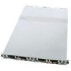
1. PCI-E Cages 2. AC Power Outlet 3. Rear NIC1 Ports 4. Rear NIC2 Ports 5. Rear UID LEDs 6. Rear UID Buttons Figure 4. Back View Buttons and System LEDs Front Panel Buttons and LEDs This server is equipped with system LED indicators, buttons, and two front panel USB ports located on the front panel. The front panel status LEDs allow constant monitoring of basic system functions while the server is operating. These LEDs provide visual cues to the status of NIC link, system health, UID (unique identifier), and power. The following figures shows the front panel: 1. NIC LED 2. System Health LED 3. Power Button 4. UID Button 5. UID LED 6. Power LED 7. HDD LED Figure 5. Front Panel Buttons and LEDs of Server Intel® Server System SR1680MV Service Guide 5
-
 1
1 -
2
-
3
-
4
-
5
-
6
-
7
-
8
-
9
-
10
-
11
-
12
-
13
-
14
-
15
-
16
-
17
-
18
-
19
-
 20
20 -
 21
21 -
 22
22 -
 23
23 -
 24
24 -
 25
25 -
 26
26 -
 27
27 -
 28
28 -
 29
29 -
 30
30 -
31
-
32
-
33
-
34
-
35
-
36
-
37
-
38
-
39
-
40
-
41
-
42
-
43
-
44
-
45
-
46
-
47
-
48
-
49
-
50
-
51
-
52
-
53
-
54
-
55
-
56
-
57
-
58
-
59
-
60
-
61
-
62
-
63
-
64
-
65
-
66
-
67
-
68
-
69
-
70
-
71
-
72
-
73
-
74
-
75
-
76
-
77
-
78
-
79
-
80
-
81
-
82
-
83
-
84
-
85
-
86
-
87
-
88
-
89
-
90
-
91
-
92
-
93
-
94
-
95
-
96
-
97
-
98
-
99
-
100
-
101
-
102
-
103
-
104
-
105
-
106
-
107
-
108
-
109
-
110
-
111
-
112
-
113
-
114
-
115
-
116
-
117
-
118
-
119
-
120
-
121
-
122
-
123
-
124
-
125
-
126
-
127
-
128
-
129
-
130
-
131
-
132
-
133
-
134
-
135
-
136
-
137
-
138
-
139
-
140
-
141
-
142
-
143
-
144
-
145
-
146
-
147
-
148
-
149
-
150
-
151
-
152
-
153
-
154
-
155
-
156
-
157
-
158
-
159
-
160
-
161
-
162
-
163
-
164
-
165
-
166
-
167
-
168
-
169
-
170
-
171
-
172
-
173
-
174
-
175
-
176
-
177
-
178
-
179
-
180
-
181
-
182
-
183
-
184
-
185
-
186
-
187
-
188
-
189
-
190
-
191
-
192
-
193
-
194
-
195
-
196
 |
 |
