Intel SR1680MV Service Guide - Page 75
Connectors and Component Locations of PDB
 |
UPC - 735858210447
View all Intel SR1680MV manuals
Add to My Manuals
Save this manual to your list of manuals |
Page 75 highlights
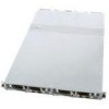
Connectors and Component Locations of PDB Figure 61. Connectors and Component Locations of PDB 1. Power Supply Slot (J1) 3. Power Connector 2 (J4) 5. Power Connector 4 (J2) 2. Power Connector 1 (J5) 4. Power Connector 3 (J3) The server board involves two system maintenance jumpers. One is MISC jumper, and the other is an ICH functions jumper. Two jumpers are divided into five pin groups (refer to Figure 62 "Location of MISC Jumper" on page -56 and Figure 63 "Location of ICH Function Jumper" on page -57. The location of two system maintenance jumpers on the motherboard is shown in the following figure: Intel® Server System SR1680MV Service Guide 55
-
 1
1 -
2
-
3
-
4
-
5
-
6
-
7
-
8
-
9
-
10
-
11
-
12
-
13
-
14
-
15
-
16
-
17
-
18
-
19
-
20
-
21
-
22
-
23
-
24
-
25
-
26
-
27
-
28
-
29
-
30
-
31
-
32
-
33
-
34
-
35
-
36
-
37
-
38
-
39
-
40
-
41
-
42
-
43
-
44
-
45
-
46
-
47
-
48
-
49
-
50
-
51
-
52
-
53
-
54
-
55
-
56
-
57
-
58
-
59
-
60
-
61
-
62
-
63
-
64
-
65
-
66
-
67
-
68
-
69
-
 70
70 -
 71
71 -
 72
72 -
 73
73 -
 74
74 -
 75
75 -
 76
76 -
 77
77 -
 78
78 -
 79
79 -
 80
80 -
81
-
82
-
83
-
84
-
85
-
86
-
87
-
88
-
89
-
90
-
91
-
92
-
93
-
94
-
95
-
96
-
97
-
98
-
99
-
100
-
101
-
102
-
103
-
104
-
105
-
106
-
107
-
108
-
109
-
110
-
111
-
112
-
113
-
114
-
115
-
116
-
117
-
118
-
119
-
120
-
121
-
122
-
123
-
124
-
125
-
126
-
127
-
128
-
129
-
130
-
131
-
132
-
133
-
134
-
135
-
136
-
137
-
138
-
139
-
140
-
141
-
142
-
143
-
144
-
145
-
146
-
147
-
148
-
149
-
150
-
151
-
152
-
153
-
154
-
155
-
156
-
157
-
158
-
159
-
160
-
161
-
162
-
163
-
164
-
165
-
166
-
167
-
168
-
169
-
170
-
171
-
172
-
173
-
174
-
175
-
176
-
177
-
178
-
179
-
180
-
181
-
182
-
183
-
184
-
185
-
186
-
187
-
188
-
189
-
190
-
191
-
192
-
193
-
194
-
195
-
196
 |
 |

Intel
®
Server System SR1680MV Service Guide
55
Connectors and Component Locations of PDB
Figure 61. Connectors and Component Locations of PDB
The server board involves two system maintenance jumpers. One is MISC jumper, and the
other is an ICH functions jumper. Two jumpers are divided into five pin groups (refer to
Figure 62 “Location of MISC Jumper” on page -56
and
Figure 63 “Location of ICH
Function Jumper” on page -57
.
The location of two system maintenance jumpers on the motherboard is shown in the
following figure:
1.
Power Supply Slot (J1)
2.
Power Connector 1 (J5)
3.
Power Connector 2
(J4)
4.
Power Connector 3 (J3)
5.
Power Connector 4
(J2)