Intel SR1680MV Service Guide - Page 69
Connector and Component Locations of IO Board
 |
UPC - 735858210447
View all Intel SR1680MV manuals
Add to My Manuals
Save this manual to your list of manuals |
Page 69 highlights
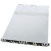
Connector and Component Locations of IO Board Figure 55. Connectors and Component Locations of IO Boards Description 1. PCI-E x8 Slots 3. System Fan1 Connectors 5. System Fan3 Connectors 7. PCI-E 1 Connectors 9. Rear UID LEDs Location Left J5 Right J5 J6 J7 J7 J8 J3 J3 CR6 CR6 Description Location 2. IO Board IO Connector 4. System Fan2 Connectors 6. PCI-E 2 Connectors 8. IO Board NIC Connectors 10. Rear UID Buttons Left J10 J8 J2 J4 SW2 Right J10 J9 J2 J4 SW2 Intel® Server System SR1680MV Service Guide 49
-
 1
1 -
2
-
3
-
4
-
5
-
6
-
7
-
8
-
9
-
10
-
11
-
12
-
13
-
14
-
15
-
16
-
17
-
18
-
19
-
20
-
21
-
22
-
23
-
24
-
25
-
26
-
27
-
28
-
29
-
30
-
31
-
32
-
33
-
34
-
35
-
36
-
37
-
38
-
39
-
40
-
41
-
42
-
43
-
44
-
45
-
46
-
47
-
48
-
49
-
50
-
51
-
52
-
53
-
54
-
55
-
56
-
57
-
58
-
59
-
60
-
61
-
62
-
63
-
 64
64 -
 65
65 -
 66
66 -
 67
67 -
 68
68 -
 69
69 -
 70
70 -
 71
71 -
 72
72 -
 73
73 -
 74
74 -
75
-
76
-
77
-
78
-
79
-
80
-
81
-
82
-
83
-
84
-
85
-
86
-
87
-
88
-
89
-
90
-
91
-
92
-
93
-
94
-
95
-
96
-
97
-
98
-
99
-
100
-
101
-
102
-
103
-
104
-
105
-
106
-
107
-
108
-
109
-
110
-
111
-
112
-
113
-
114
-
115
-
116
-
117
-
118
-
119
-
120
-
121
-
122
-
123
-
124
-
125
-
126
-
127
-
128
-
129
-
130
-
131
-
132
-
133
-
134
-
135
-
136
-
137
-
138
-
139
-
140
-
141
-
142
-
143
-
144
-
145
-
146
-
147
-
148
-
149
-
150
-
151
-
152
-
153
-
154
-
155
-
156
-
157
-
158
-
159
-
160
-
161
-
162
-
163
-
164
-
165
-
166
-
167
-
168
-
169
-
170
-
171
-
172
-
173
-
174
-
175
-
176
-
177
-
178
-
179
-
180
-
181
-
182
-
183
-
184
-
185
-
186
-
187
-
188
-
189
-
190
-
191
-
192
-
193
-
194
-
195
-
196
 |
 |

Intel
®
Server System SR1680MV Service Guide
49
Connector and Component Locations of IO Board
Figure 55. Connectors and Component Locations of IO Boards
Description
Location
Description
Location
Left
Right
Left
Right
1.
PCI-E x8 Slots
J5
J5
2.
IO Board IO
Connector
J10
J10
3.
System Fan1
Connectors
J6
J7
4.
System Fan2
Connectors
J8
J9
5.
System Fan3
Connectors
J7
J8
6.
PCI-E 2
Connectors
J2
J2
7.
PCI-E 1
Connectors
J3
J3
8.
IO Board NIC
Connectors
J4
J4
9.
Rear UID LEDs
CR6
CR6
10. Rear UID
Buttons
SW2
SW2