Intermec PB51 Fingerprint Developer's Guide (old) - Page 96
About Insertion and Anchor Points, Fingerprint Command Reference Manual.
 |
View all Intermec PB51 manuals
Add to My Manuals
Save this manual to your list of manuals |
Page 96 highlights
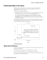
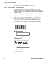
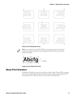
Chapter 6 - Designing Bar Code Labels Dots are the same size along both the X-axis and the Y-axis. About Insertion and Anchor Points The insertion point of any field is specified using a PRPOS, statement. For example, the statement PRPOS 100, 200 means that the object is inserted at a position 100 dots to the right of the origin and 200 dots further back along the media path. Each field has up to 9 anchor points. Use the ALIGN command to choose the anchor point that is positioned at the insertion point. For example, specifying ALIGN 1 places the lower left corner of a text field at the insertion point.. Note: For detailed information on the anchor points of bar codes where the interpretation is an integrated part of the bar code pattern (such as for EAN and UPC codes), see ALIGN in the Fingerprint Command Reference Manual. The next illustrations show the anchor point locations for the different fields. 5 7 8 9 4 6 1 2 3 Bar Code Field Anchor Points 1, 4, or 7 2, 5, or 8 Box Field Anchor Points 7 8 5 4 1 2 Image Field Anchor Points 1, 4, or 7 2, 5, or 8 Line Field Anchor Points 3, 6, or 9 9 6 3 3, 6, or 9 80 Intermec Fingerprint Developer's Guide
-
 1
1 -
2
-
3
-
4
-
5
-
6
-
7
-
8
-
9
-
10
-
11
-
12
-
13
-
14
-
15
-
16
-
17
-
18
-
19
-
20
-
21
-
22
-
23
-
24
-
25
-
26
-
27
-
28
-
29
-
30
-
31
-
32
-
33
-
34
-
35
-
36
-
37
-
38
-
39
-
40
-
41
-
42
-
43
-
44
-
45
-
46
-
47
-
48
-
49
-
50
-
51
-
52
-
53
-
54
-
55
-
56
-
57
-
58
-
59
-
60
-
61
-
62
-
63
-
64
-
65
-
66
-
67
-
68
-
69
-
70
-
71
-
72
-
73
-
74
-
75
-
76
-
77
-
78
-
79
-
80
-
81
-
82
-
83
-
84
-
85
-
86
-
87
-
88
-
89
-
90
-
 91
91 -
 92
92 -
 93
93 -
 94
94 -
 95
95 -
 96
96 -
 97
97 -
 98
98 -
 99
99 -
 100
100 -
 101
101 -
102
-
103
-
104
-
105
-
106
-
107
-
108
-
109
-
110
-
111
-
112
-
113
-
114
-
115
-
116
-
117
-
118
-
119
-
120
-
121
-
122
-
123
-
124
-
125
-
126
-
127
-
128
-
129
-
130
-
131
-
132
-
133
-
134
-
135
-
136
-
137
-
138
-
139
-
140
-
141
-
142
-
143
-
144
-
145
-
146
-
147
-
148
-
149
-
150
-
151
-
152
-
153
-
154
-
155
-
156
-
157
-
158
-
159
-
160
-
161
-
162
-
163
-
164
-
165
-
166
-
167
-
168
-
169
-
170
-
171
-
172
-
173
-
174
-
175
-
176
-
177
-
178
-
179
-
180
-
181
-
182
-
183
-
184
-
185
-
186
-
187
 |
 |
