Intermec PX4i Double Serial Interface Kit Installation Instructions - Page 10
face board to the hexagonal spacer on the CPU board.
 |
View all Intermec PX4i manuals
Add to My Manuals
Save this manual to your list of manuals |
Page 10 highlights
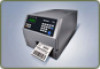
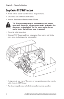
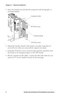
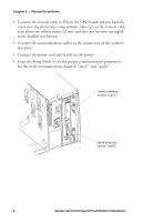
Chapter 2 - Physical Installation • Insert the interface board with the component side facing right, as seen from behind. Component side #T10 Torx screw Interface board #T10 Torx screw • Attach the interface board to the printer's rear plate using the two screws left over when you removed the original cover plate. • Using the #T20 Torx screw you previously removed, attach the interface board to the hexagonal spacer on the CPU board. • The kit contains two flat cables. Connect the flat cable with two connectors to P1 on the interface board, see the next page. 6 Double Serial Interface Kit Installation Instructions
-
 1
1 -
2
-
3
-
4
-
 5
5 -
 6
6 -
 7
7 -
 8
8 -
 9
9 -
 10
10 -
 11
11 -
 12
12 -
 13
13 -
 14
14 -
 15
15 -
16
-
17
-
18
-
19
-
20
-
21
-
22
-
23
-
24
-
25
-
26
-
27
-
28
-
29
-
30
-
31
-
32
-
33
-
34
-
35
-
36
-
37
-
38
-
39
-
40
 |
 |

6
Double Serial Interface Kit Installation Instructions
Chapter 2 — Physical Installation
•
Insert the interface board with the component side facing right, as
seen from behind.
•
Attach the interface board to the printer’s rear plate using the two
screws left over when you removed the original cover plate.
•
Using the #T20 Torx screw you previously removed, attach the inter-
face board to the hexagonal spacer on the CPU board.
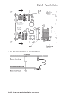
•
°e kit contains two flat cables. Connect the flat cable with two con-
nectors to P1 on the interface board, see the next page.
Interface board
Component side
#T10 Torx screw
#T10 Torx screw