Intermec PX4i Double Serial Interface Kit Installation Instructions - Page 20
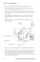
Installation of one board: Attach the interface board in the innermost
 |
View all Intermec PX4i manuals
Add to My Manuals
Save this manual to your list of manuals |
Page 20 highlights
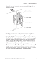
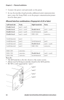
Chapter 2 - Physical Installation • Save the cover plate(s) for possible later use. Keep the screws. • Remove the #T20 Torx screw fitted on the hexagonal spacer at the center of the CPU board. Keep the screw. • If necessary, reconfigure the interface board by fitting or removing circuits and straps according to the descriptions of each board later in this chapter. • Attach the flat cable included in the kit to connector J62 (marked "EXP BOARD") on the CPU board (see illustration on the next page). • Insert the interface board with the component side facing right, as seen from behind. Existing spacer Spacer (only in case of two boards) #T10 Torx screw (2 + 2) Interface boards #T20 Torx screw Connect to J62 Illustration shows installation of one IEEE 1284 and one Double Serial interface board. • Installation of one board: Attach the interface board in the innermost slot in the printer's rear plate using the two screws left over when you removed the original cover plate. Using the #T20 Torx screw you previously removed, attach the interface board to the hexagonal spacer at the center of the CPU board. 16 Double Serial Interface Kit Installation Instructions
-
 1
1 -
2
-
3
-
4
-
5
-
6
-
7
-
8
-
9
-
10
-
11
-
12
-
13
-
14
-
 15
15 -
 16
16 -
 17
17 -
 18
18 -
 19
19 -
 20
20 -
 21
21 -
 22
22 -
 23
23 -
 24
24 -
 25
25 -
26
-
27
-
28
-
29
-
30
-
31
-
32
-
33
-
34
-
35
-
36
-
37
-
38
-
39
-
40
 |
 |
