Intermec PX4i Double Serial Interface Kit Installation Instructions - Page 9
circuits and straps according to the descriptions in s 3 and 4.
 |
View all Intermec PX4i manuals
Add to My Manuals
Save this manual to your list of manuals |
Page 9 highlights
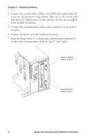
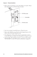
Chapter 2 - Physical Installation • Remove the two #T10 Torx screws that hold the interface cover plate. Remove the cover plate. #T10 Torx screw Cover plate #T10 Torx screw • Save the cover plate for possible later use. Keep the screws. • Remove the #T20 Torx screw fitted on the hexagonal spacer at the CPU board. Keep the screw. • If reconfiguration of the interface board is required, fit or remove circuits and straps according to the descriptions in Chapters 3 and 4. • Attach the flat cable included in the kit to connector J62 (marked "EXP BOARD") on the CPU board (see page 7). Double Serial Interface Kit Installation Instructions 5
-
 1
1 -
2
-
3
-
 4
4 -
 5
5 -
 6
6 -
 7
7 -
 8
8 -
 9
9 -
 10
10 -
 11
11 -
 12
12 -
 13
13 -
 14
14 -
15
-
16
-
17
-
18
-
19
-
20
-
21
-
22
-
23
-
24
-
25
-
26
-
27
-
28
-
29
-
30
-
31
-
32
-
33
-
34
-
35
-
36
-
37
-
38
-
39
-
40
 |
 |

Double Serial Interface Kit Installation Instructions
5
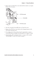
Chapter 2 — Physical Installation
•
Remove the two #T10 Torx screws that hold the interface cover plate.
Remove the cover plate.
•
Save the cover plate for possible later use. Keep the screws.
•
Remove the #T20 Torx screw fitted on the hexagonal spacer at the
CPU board. Keep the screw.
•
If reconfiguration of the interface board is required, fit or remove
circuits and straps according to the descriptions in Chapters 3 and 4.
•
Attach the flat cable included in the kit to connector J62 (marked
“EXP BOARD”) on the CPU board (see page 7).
#T10 Torx screw
Cover plate
#T10 Torx screw