Intermec PX4i Double Serial Interface Kit Installation Instructions - Page 25
Double Serial Interface Kit Installation Instructions
 |
View all Intermec PX4i manuals
Add to My Manuals
Save this manual to your list of manuals |
Page 25 highlights
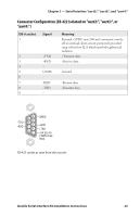
Chapter 3 - Serial Interface "uart2:", "uart3:", and "uart4:" Connector Configuration (RS-232 on "uart2:", "uart3:", or "uart4:") DB-9 socket 1 Signal 2 TXD 3 RXD 4 DSR 5 GND 6 DTR 7 CTS 8 RTS 9 - Meaning External +5VDC max 500 mA (automatic switchoff at overload, short-circuit protected) Transmit data Receive data Data set ready Ground Data terminal ready Clear to send Request to send Not used 5 GND 9 4 DSR RTS 8 CTS 3 7 RXD 2 TXD DTR 6 1 +5V (0.5 RS-232 socket as seen from the outside. Double Serial Interface Kit Installation Instructions 21
-
 1
1 -
2
-
3
-
4
-
5
-
6
-
7
-
8
-
9
-
10
-
11
-
12
-
13
-
14
-
15
-
16
-
17
-
18
-
19
-
 20
20 -
 21
21 -
 22
22 -
 23
23 -
 24
24 -
 25
25 -
 26
26 -
 27
27 -
 28
28 -
 29
29 -
 30
30 -
31
-
32
-
33
-
34
-
35
-
36
-
37
-
38
-
39
-
40
 |
 |

4
5
3
2
1
8
9
7
6
TXD
+5V (0.5
RXD
DSR
GND
DTR
CTS
RTS
Double Serial Interface Kit Installation Instructions
21
Chapter 3 — Serial Interface "uart2:", "uart3:", and "uart4:"
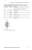
Connector Configuration (RS-232 on "uart2:", "uart3:", or "uart4:")
DB-9 socket
Signal
Meaning
1
External +5VDC max 500 mA (automatic switch-
off
at overload, short-circuit protected)
2
TXD
Transmit data
3
RXD
Receive data
4
DSR
Data set ready
5
GND
Ground
6
DTR
Data terminal ready
7
CTS
Clear to send
8
RTS
Request to send
9
–
Not used
RS-232 socket as seen from the outside.