Intermec PX4i Double Serial Interface Kit Installation Instructions - Page 19
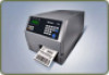
EasyCoder PX4i and PX6i Printers
 |
View all Intermec PX4i manuals
Add to My Manuals
Save this manual to your list of manuals |
Page 19 highlights
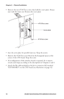
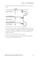
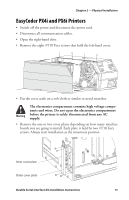
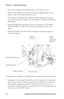
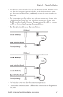
Chapter 2 - Physical Installation EasyCoder PX4i and PX6i Printers • Switch off the power and disconnect the power cord. • Disconnect all communication cables. • Open the right-hand door. • Remove the eight #T10 Torx screws that hold the left-hand cover. • Put the cover aside on a soft cloth or similar to avoid scratches. The electronics compartment contains high voltage components and wires. Do not open the electronics compartment before the printer is safely disconnected from any AC supply. • Remove the one or two cover plates depending on how many interface boards you are going to install. Each plate is held by two #T10 Torx screws. Always start installation at the innermost position. Inner cover plate Outer cover plate Double Serial Interface Kit Installation Instructions 15
-
 1
1 -
2
-
3
-
4
-
5
-
6
-
7
-
8
-
9
-
10
-
11
-
12
-
13
-
 14
14 -
 15
15 -
 16
16 -
 17
17 -
 18
18 -
 19
19 -
 20
20 -
 21
21 -
 22
22 -
 23
23 -
 24
24 -
25
-
26
-
27
-
28
-
29
-
30
-
31
-
32
-
33
-
34
-
35
-
36
-
37
-
38
-
39
-
40
 |
 |
