JVC DT100U Instruction Manual - Page 69
POWER SAVE, S-VHS MODE, AV COMPU, When this function is set to
 |
UPC - 046838015267
View all JVC DT100U manuals
Add to My Manuals
Save this manual to your list of manuals |
Page 69 highlights
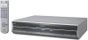
EN 69 *The default setting is bold in the table below. L "POWER SAVE" "ON" "OFF" When this function is set to "ON", you can reduce the power consumption. While the VCR is turned off, the front display panel does not show the clock. When this function is set to "ON", an i.LINK device cannot be recognized. As a result, it is not possible to record a program using the digital tuner's* timer function. In addition the device does not pass along data if it is in a branched connection. *For details of a digital tuner, refer to the instruction manual of the digital tuner. NOTE: It takes some time until VCR completes its set up when you turn on the VCR. L "S-VHS MODE" "ON" "OFF" You can determine which recording mode - either S-VHS mode or VHS mode - is used for recording on D-VHS and S-VHS tapes. When this function is set to "ON", you can record on D-VHS and S-VHS tapes with SVHS picture quality. When this function is set to "OFF", you can record on D-VHS and S-VHS tapes with VHS picture quality. NOTES: • To record in S-VHS/VHS mode on D-VHS tape, press [D-VHS] to turn off the [D-VHS] indicator. • S-VHS mode allows you to make high quality video recordings with horizontal resolution of 400 lines, comparing with the 230 lines of resolution of conventional VHS recordings. To achieve the highest quality picture we recommend to record in S-VHS mode. (But remember that a conventional VHS VCR without SQPB cannot play back S-VHS tapes recorded in S-VHS mode.) • S-VHS MODE setting does not affect recording on VHS tapes. Recording on VHS tapes is always performed in VHS mode except when using S-VHS ET mode (A page 70). L "AV COMPULINK" "ON" "OFF" The [REMOTE PAUSE/AV COMPULINK] terminal on the rear panel can be used as either the [REMOTE PAUSE] terminal or the [AV COMPULINK] terminal. When this function is set to "ON", you can use this terminal as the [AV COMPULINK] terminal. By connecting other JVC's [AV COMPULINK] components (see the diagram below), including amplifiers (or receivers) and televisions, one touch control of the audio and video components linked via their [AV COMPULINK] connectors becomes possible. For example : simply load a cassette in the VCR and press [PLAY (I)] so that the [AV COMPULINK] components automatically turn on, the TV's AV mode is selected and the VCR starts playback. (You do not have to press [PLAY (I)] if the cassette's record safety tab is removed.) When this function is set to "OFF", you can use this terminal as the [REMOTE PAUSE] terminal (A page 83). NOTES: • When the remote control code is set to C or D, the connector cannot be used as [AV COMPULINK] terminal even if "AV COMPU-LINK" is set to "ON". It is recommended to set the remote control code to A when you use this function. (A page 86) • Connection varies depending on the type of JVC TV you have. Refer to the TV's instruction manual when making this connection. JVC TV with AV COMPULINK To Audio in i.LINK IN/OUT DV IN HDMI OUT OPTICAL S400 D-THEATER REGION 1 PCM/STREAM DIGITAL AUDIO OUT This VCR Y PB/CB PR/CR COMPONENT VIDEO OUT S-VIDEO S-VIDEO ATSC IN VIDEO VIDEO L AUDIO R OUTPUT L AUDIO R L-1 L-2 INPUT CABLE BOX REMOTE PAUSE/ AV COMPULINK VHF/UHF ANTENNA IN OUT ANTENNA To AV COMPULINK (VCR ONLY) To S-video in To [S VIDEO OUTPUT] S-video cable (supplied) Audio cable (supplied) Mini-plug cable (not supplied) To [AUDIO OUTPUT] To [REMOTE PAUSE/AV COMPULINK]
-
 1
1 -
2
-
3
-
4
-
5
-
6
-
7
-
8
-
9
-
10
-
11
-
12
-
13
-
14
-
15
-
16
-
17
-
18
-
19
-
20
-
21
-
22
-
23
-
24
-
25
-
26
-
27
-
28
-
29
-
30
-
31
-
32
-
33
-
34
-
35
-
36
-
37
-
38
-
39
-
40
-
41
-
42
-
43
-
44
-
45
-
46
-
47
-
48
-
49
-
50
-
51
-
52
-
53
-
54
-
55
-
56
-
57
-
58
-
59
-
60
-
61
-
62
-
63
-
 64
64 -
 65
65 -
 66
66 -
 67
67 -
 68
68 -
 69
69 -
 70
70 -
 71
71 -
 72
72 -
 73
73 -
 74
74 -
75
-
76
-
77
-
78
-
79
-
80
-
81
-
82
-
83
-
84
-
85
-
86
-
87
-
88
-
89
-
90
-
91
-
92
-
93
-
94
-
95
-
96
-
97
-
98
-
99
-
100
 |
 |