JVC GY-DV500E Instruction Manual - Page 10
Top Left Side - gy dv500 camcorder
 |
View all JVC GY-DV500E manuals
Add to My Manuals
Save this manual to your list of manuals |
Page 10 highlights
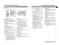
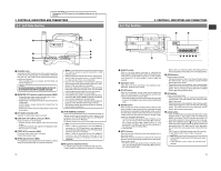
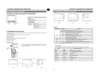
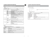
For servicing The protocol of VCR control is not included in this service ← manual. 2. CONTROLS, INDICATORS AND CONNECTORS 2-3 Left Side Section q w e r PUSH DV CAMCORDER GY-DV500 Y/C OUT MONITOR OUT LINE OUT CH-1 CH-2 VTR REMOTE SYNC IN TEST OUT MIC IN LENS i u y t 1 Cassette cover Pressing the EJECT switch on top of the section opens this cover so that a videocassette can be inserted or removed from the unit. The cover can be locked automatically by pushing and closing it. * If the cassette cover is not closed, the GY-DV500 will remain inoperative. Memo: To prevent penetration of foreign objects into the unit, do not leave the unit with the cassette cover open. 2 [MONITOR OUT] monitor output connector (BNC) • Composite video signal output with setup (for U-ver.). Composite video signal output (E-ver.). • An EE image or the playback image is output through the VCR section. An EE image is output during other modes than the playback mode. * Data for the Camera and VCR setup menus or time code is not output. 3 [Y/C OUT] connector (4P) Separate YC video signal output connector. 4 [LINE OUT CH-1/CH-2] connector (RCA) Output connector for audio signals. • Outputs the input audio signal in the record and stop modes. • Outputs the playback audio signal in the playback mode. • Alarm sound is not output. 5 [TEST OUT] connector (BNC) Composite video signal output connector. Outputs the camera image. 6 [SYNC.IN] connector (BNC) For inputting the sync signal when the GY-DV500's camera image is synchronized with an external component. Memo: • The camera cannot be synchronized with a VCR playback signal. • When the power is switched ON while an external sync signal is input, the screen moves in a vertical direction for a few seconds. This is not a malfunction. • Only for the combined H (horizontal)/V (vertical) synchronizing signal. Synchronization with the SC (subcarrier) of the input signal is not possible. Even if SC adjustment is performed, a phase shift will take place at the time of power on/off. The SC phase must be adjusted each time the power is turned on. • Color frame synchronization is not possible. • If the external sync signal is disrupted during recording, the "SYNC INH" (SYNC INHIBIT) indicator is displayed on the counter display and recording stops. • If the external sync signal is disrupted during playback, playback of the disturbed video image continues. Start playback again after synchronization is obtained and the signal is stabilized. [VTR REMOTE] connector A part of the unit's functions can be controlled externally. To remote control the unit using the control signal of this connector, the VCR Setup Menu item No. 050 REMOTE SELECT must be set to "RS232C". For details, please consult your JVC dealer. Note: • When a cable is connected to the VTR REMOTE connector, the VTR Setup Menu is not displayed in the viewfinder. Make settings on the VTR Setup Menu while the cable is not connected. • When a cable is connected to the VTR REMOTE connector, the VCR operation mode will not be displayed correctly on the Status 1 screen in the viewfinder. 8 Microphone attachment holes For attaching the microphone holder KA-A50 (optional). See "Attaching the Microphone (optional)" on page 32. 18 2-4 Top Section 2. CONTROLS, INDICATORS AND CONNECTORS q w PUSH OPEN w EJECT LOG REW STOP FF PLAY STILL i y ruet 1 [EJECT] switch Slide to the side when inserting or ejecting the videocassette. Sliding this switch opens the cassette cover. If the switch is moved while the power is off, the cassette cover opens but it is not possible to insert or eject the cassette. 2 Operation cover Open this cover when operating in the playback mode. Otherwise, keep this cover closed. 3 [PLAY] button Press to start playback. In play mode, the unit outputs the video and audio signals of normal playback and the LED indicator above the PLAY button lights. * If the auto tracking is active at the moment the play mode is entered, the playback video will be interfered with digital noise. 4 [STOP] button Press to enter stop mode. The drum keeps rotating in stop mode. However, when stop mode has continued for about 30 minutes, the unit enters the tape protect mode, in which the drum stops rotation and the tape tensioner is released. It takes more time than usual to enter the record or play mode from the tape protect mode. * The time until the tape protect mode is initiated can be set to 3 or 30 minutes with the VCR Setup Menu item No. 307 LONG PAUSE TIME. When used in a cold environment, the setting will be 3 minutes regardless of the setting on the VCR Setup Menu. See page 69. 5 [STILL] button Press to enter the still picture mode during playback or in the search mode. When the still picture mode has continued for about 30 minutes, the unit automatically switches to the stop mode. (Tape protect mode) * The time until the tape protect mode is initiated can be set to 3 or 30 minutes with the VCR Setup Menu item No. 307 LONG PAUSE TIME. When used in a cold environment, the setting will be 3 minutes regardless of the setting on the VCR Setup Menu. 6 [REW] button Press to rewind the tape. • Pressing the button in stop or fast forward mode initiates the rewind mode. The LED indicator above the REW button lights in this mode. • Pressing the button during playback, still or forward search initiates reverse search at about 10 times the normal play speed. The LED indicators above the PLAY and REW buttons light during reverse search. 7 [FF] button Press to fast forward tape. • Pressing the button in stop or rewind mode initiates fast forward mode. The LED indicator above the FF button lights in this mode. • Pressing the button during playback, still or reverse search initiates forward search at about 10 times the normal play speed. The LED indicators above the PLAY and FF buttons light during forward search. 8 [LOG] button • When the REW button is pressed while this button is kept pressed, the S.S.F. data stored in the unit's memory are written to the tape. The LED indicator above the LOG button lights while S.S.F. data is being written to the tape. • When the CONTINUE button (6 on page 15) is pressed while this button is kept pressed in the stop mode, the tape winds to the S.S.F. data's last OUT point, after which the unit enters the record-pause mode. (Scene End Cue Up) The FF button's LED blinks during Scene End Cue Up. See "Writing S.S.F. Data to Tape" on page 63. CAUTION: • Only the EJECT switch and STOP button work during recording. • If the cassette cover is open, all operations are rejected. 19
-
 1
1 -
2
-
3
-
4
-
 5
5 -
 6
6 -
 7
7 -
 8
8 -
 9
9 -
 10
10 -
 11
11 -
 12
12 -
 13
13 -
 14
14 -
 15
15 -
16
-
17
-
18
-
19
-
20
-
21
-
22
-
23
-
24
-
25
-
26
-
27
-
28
-
29
-
30
-
31
-
32
-
33
-
34
-
35
-
36
-
37
-
38
-
39
-
40
-
41
-
42
-
43
-
44
-
45
-
46
-
47
-
48
 |
 |
