JVC GY-DV500E Instruction Manual - Page 9
VCR Display - service manual
 |
View all JVC GY-DV500E manuals
Add to My Manuals
Save this manual to your list of manuals |
Page 9 highlights
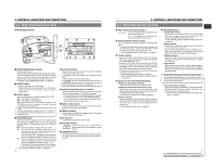
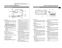
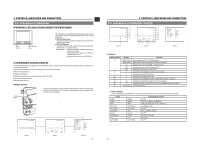
2. CONTROLS, INDICATORS AND CONNECTORS 2-2 Right Side Section (Cont'd) [VCR Display Section] 21 FILTER 1 3200k 2 5600k 3 5600k+ND SHUTTER STATUS MENU ALARM MONITOR AUTO IRIS FULL AUTO BLACK BACK L NORMAL SPOT L STRETCH NORMAL COMPRESS LOLUX PRST A B ON KNEE OFF AUTO BARS CAM HML SAVE STBY VTR GAIN OUTPUT WHT.BAL NG POWER ON OFF OPERATE/WARNING RESET MONITOR SELECT CH-1 AUDIO CH-2 LEVEL LIGHT ON OFF COUNTER CTL TC UB 6 5 FE CH 1 OVER AUTO OFF DEW 3 CH 2 40 30 20 10 0 dB OVER SERVO RF L i 7 32k 48k AUD LOCK SP PB NDF HOLD 4 8 MENU REMAIN H M S F REV FWD E BATT F H M 90 A B CD 1 [OPERATE/WARNING] indicator Normally lights green. Lights orange during the VTR SAVE (tape protect) mode. This indicator lights or blinks in red in the case of a warning condition related to the remaining tape time, remaining battery power or other abnormal condition in the unit. For details, see "ALARM INDICATIONS" on pages 86. 2 [RESET] button • Press to reset the CTL counter value. • Pressing the button during presetting of time code or user's bit resets the time code or user's bit data to "00:00:00:00". 3 [LIGHT] switch Turns the illumination of the back-lit display ON or OFF. ON : The display is illuminated. OFF : The display is not illuminated. (Keep this switch at OFF during battery operation of the GY-DV500 or when it is required to reduce the power consumption for some reason.) Note: When a videocassette is loaded and the VTR switch is set to SAVE mode, the illumination will go out even if the backlight is ON. 4 [COUNTER] switch Selects the contents displayed on the LCD counter display. The displayed contents when TC or UB is set can be selected using the VCR Setup Menu item No. 516 DISPLAY SELECT. CTL : Set to this position to display the CTL counter. TC : Set to this position to display time codes or for presetting the time code. (When the Menu item No. 516 DISPLAY SELECT is set to "TC".) Time (Hour, Min., Sec.) is displayed. (When the Menu item No. 516 DISPLAY SELECT is set to "CLOCK".) UB : Set to this position to display the user's bits of time codes or presetting the user's bit. (When the Menu item No. 516 DISPLAY SELECT is set to "TC".) Date (Month, Day, Year) is displayed. (When the Menu item No. 516 DISPLAY SELECT is set to "CLOCK".) See "VCR Setup Menu Contents" on page 69. 16 5 Audio level meters Show the audio input level of the CH-1 and CH-2 channels in the record mode or EE mode. In the playback mode, the meters show the playback audio level. "OVER" lights in case of excessive input. CAUTION: Immediately after the power is switched ON, the level meters may fluctuate. This is not a malfunction. 6 32K/48K sampling frequency indication Indicates whether audio recording or playback occurs with 12-bit, 32 kHz sampling or 16-bit 48 kHz sampling. • In the recording mode, the sampling frequency is set using the VCR Setup Menu item No. 245 SAMPLING RATE. In the playback mode, the indication conforms to the sampling rate of the recorded sound. 7 [AUD LOCK] indicator Indicates whether the audio signal is locked to the video signal during recording and playback. 8 [MENU] indicator Appears when the MENU button 1 on page 15 is pressed to select the VCR Setup Menu. 9 SP indicator Indicates the tape speed in record mode. 0 Cassette indicator Lights when the unit is loaded with a videocassette. Blinks during ejection or tape loading. ! [REMAIN] indicator The remaining tape time (minutes and seconds) is shown. For details, see page "Remaining Tape Time Display" on page 22. 2. CONTROLS, INDICATORS AND CONNECTORS 2-2 Right Side Section (Cont'd) @ Tape transport direction indicators REV FWD One of the indicators lights according to the tape transport direction. is displayed in the record-pause mode and in the still picture mode. # Remaining Battery Power Display The 7-dot segment bar display shows the remaining battery power. * To display the remaining battery power accurately, set the VCR Setup Menu item No. 396 BATTERY TYPE according to the type of the battery pack in use. See "Remaining Battery Power Display" on page 22. $ Counter display • Usually, this section shows the data of the CTL counter, time code or user's bit. The display mode can be selected with the 4 COUNTER switch. • Displays the VCR setup menu data when the GY-DV500 is in the VCR setup menu mode by pressing the MENU button 1 on page 15. The VCR setup menu includes the hour meter (accumulated drum operating time). • This section shows an error code when an abnormal condition occurs with the unit. See "Counter Display Contents" on page 22. See "TROUBLES WITH ERROR CODE OUTPUTS" on page 90. % Section for time code related indications [PB] Time code playback indicator Lights when the time code is in playback mode. [NDF] Non-drop frame indicator (U-ver. only) Lights when the internal time code generator or the playback time code framing mode is non-drop frame. "DF" is displayed in the drop-frame mode. • It never lights when the CTL counter is displayed. [HOLD] indicator Lights when the time code generator display is held by pressing the HOLD button in the time code setting block. The time code or user's bit can be preset while this indicator is lit. See "Displaying Time Code" on page 56. ^ Warning indicators [AUTO OFF] indicator Lights when a non-recoverable error (e.g. tape winding error, drum stopped, etc.) occurs with the unit. This indicator also lights if condensation occurs. See "TROUBLES WITH ERROR CODE OUTPUTS" on page 90. [DEW] indicator Lights when condensation (dewing) occurs on the drum or other mechanism in the unit. The unit rejects all operations while this indicator is lit. When the condensation has disappeared, the indicator turns off and the unit accepts operations again. [SERVO] indicator Lights in the case of trouble with the drum servo during recording to indicate that normal recording is not being accomplished. [RF] indicator Lights when the video head is clogged. Head clogging is detected during playback and recording check using the RET button on the lens section. Note that it is not detected during recording. * Should this indicator light up, clean the head using the provided head cleaning tape. For instructions on head cleaning tape, read the separate sheet "Precautions for Use of Head Cleaning Tape". [Li] Lithium battery indicator Lights and indicates the necessity of replacement when the lithium battery that backs up data of the built-in time code generator is nearly exhausted. See "Inserting and Replacing Backup Lithium Batteries" on page 34. 17 For servicing See the service manual page 2-7 "2.4.3 Cleaning". ←
-
 1
1 -
2
-
3
-
 4
4 -
 5
5 -
 6
6 -
 7
7 -
 8
8 -
 9
9 -
 10
10 -
 11
11 -
 12
12 -
 13
13 -
 14
14 -
15
-
16
-
17
-
18
-
19
-
20
-
21
-
22
-
23
-
24
-
25
-
26
-
27
-
28
-
29
-
30
-
31
-
32
-
33
-
34
-
35
-
36
-
37
-
38
-
39
-
40
-
41
-
42
-
43
-
44
-
45
-
46
-
47
-
48
 |
 |
