JVC GY-DV500E Instruction Manual - Page 22
Setting the Date and Time, Camera Settings
 |
View all JVC GY-DV500E manuals
Add to My Manuals
Save this manual to your list of manuals |
Page 22 highlights
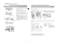
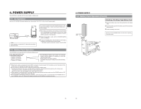
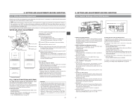
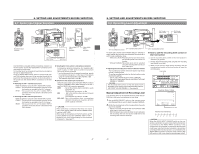
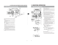
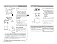
5. PREPARATIONS 5-3 Setting the Date and Time The date and time of the built-in clock should be set. During shooting, the date and time data are recorded in the sub-time code area on the tape. During playback, the data are shown on the counter display. Powered by the backup lithium battery, the set date and time data continue to count even when the power is switched off. Check that the lithium battery has been inserted. M ONITOR OPERATE/WARNING RESET MONITOR SELECT CH 1 CH 2 40 30 20 32k 48k AUD LOCK SP MENU REMAIN H OVER AUTO OFF DEW 10 0 dB OVER SERVO RF L i PB NDF HOLD H M S F REV FWD E BATT F M LIGHT ON OFF COUNTER CTL TC UB CH-1 AUDIO CH-2 LEVEL 2. COUNTER switch CH-1 AUDIO LEVEL CH-2 LITHIUM BATT. CH-1 CH-2 TC GENERATOR AUTO MANUAL PRESET REGEN AUDIO SELECT FREE REC AUDIO INPUT CH-1 CH-2 CONTINUE MENU FRONT REAR GROUP HOLD ITEM SELECT DATA SET SHIFT ADVANCE PRESET 3. HOLD button 4. SHIFT button Lithium battery compartment 5. PRESET button 4. ADVANCE button Time display (COUNTER switch: TC) Hour Min. Sec. HOLD H M S HOLD H M S H M S Date display (COUNTER switch: UB) Month Day Year HOLD HOLD 1. Turn ON the power and set the counter display to the date/ time mode. • Set the VCR Setup Menu item No. 516 DISPLAY SELECT to "CLOCK". See "Displaying and Setting VCR Setup Menus" on page 67. See "VCR Setup Menu" on page 69. 2. Set the COUNTER switch to TC or UB. To set the time: Set the switch to TC. The time (Hour, Min., Sec.) is indicated on the counter display. (24-hour clock system) To set the date: Set the switch to UB. The date (Month, Day, Year) is indicated on the counter display. 3. Press the HOLD button to enter the setting mode. The "HOLD" indicator lights up on the display to indicate that the unit is in the setting mode. The leftmost digit on the counter blinks. 4. Set the date and time. • Each time the ADVANCE button is pressed, the value of the blinking digit increases. • Each time the SHIFT button is pressed, the digit to the right of the currently blinking one starts blinking. When pressed while the rightmost digit is blinking, the leftmost digit starts blinking again. Repeat the above procedure to set the value of all the digits. 5. To decide the set date and time data, press the PRESET button. The "HOLD" indicator on the display turns off and the date/ time display stops blinking. The time starts counting. Memo: To display and set the time code or user's bit, set the VCR Setup Menu item No. 516 DISPLAY SELECT to "TC". 41 6. SETTING AND ADJUSTMENTS BEFORE SHOOTING 6-1 Camera Settings 3. FILTER 1 3200k 2 5600k 3 5600k+ND SHUTTER STATUS MENU ALARM MONITOR AUTO IRIS FULL AUTO BLACK BACK L NORMAL SPOT L STRETCH NORMAL COMPRESS LOLUX PRST A B ON KNEE OFF AUTO BARS CAM HML SAVE STBY VTR GAIN OUTPUT WHT.BAL NG POWER ON OFF OPERATE/WARNING RESET MONITOR SELECT CH-1 AUDIO CH-2 LEVEL 2. AUTO IRIS FULL AUTO BLACK BACK L NORMAL SPOT L STRETCH NORMAL COMPRESS LOLUX 1. NG POWER ON OFF PRST A B ON KNEE OFF AUTO BARS CAM HML SAVE STBY VTR GAIN OUTPUT WHT.BAL BA C D E 1. POWER ON 1 First place a charged battery pack in the battery case on the rear section of the unit. If battery pack is not used, connect DC power to the DC INPUT connector on the rear section of the unit using the AC power adapter (AA- LIGHT ON OFF P250) to supply DC 12 V current. COUNTER CTL TC UB 2 Set the POWER switch on the unit to ON. 2. SWITCH positions A. Set the VTR switch to STBY. B. AUTO IRIS switch; set to NORMAL. C. GAIN switch; set to L. The L position is 0 dB. D. OUTPUT switch; set to CAM\AUTO KNEE OFF. E. WHT. BAL (Auto White Balance) switch; set to A or B. 3. Set the lens' iris mode switch to "A" (AUTO IRIS side) 4. Choose the proper color temperature conversion filter. FILTER 1 3200K 2 5600K 3 5600K+ND Suitable Location Indoors, dark outdoors Outdoors Outdoors under clear sky 5. Using the SHUTTER dial, set the shutter speed to OFF. VF OFF ZEBRA SKIN ON AREA AUTO WHITE ACCU FOCUS VTR AUDIO LEVEL CH-1 TAKE 4. 5. 42
-
 1
1 -
2
-
3
-
4
-
5
-
6
-
7
-
8
-
9
-
10
-
11
-
12
-
13
-
14
-
15
-
16
-
 17
17 -
 18
18 -
 19
19 -
 20
20 -
 21
21 -
 22
22 -
 23
23 -
 24
24 -
 25
25 -
 26
26 -
 27
27 -
28
-
29
-
30
-
31
-
32
-
33
-
34
-
35
-
36
-
37
-
38
-
39
-
40
-
41
-
42
-
43
-
44
-
45
-
46
-
47
-
48
 |
 |
